Abstract: The design confirmation test for wellhead device and Christmas tree valves is a crucial method for verifying reliability. Using an established test system and procedures, the valve is tested to determine if it meets the required reliability indices.
Testing more than 40 valves has led to continuous improvements in design, materials, and manufacturing processes, enhancing product reliability, ensuring compliance with standards, and expanding market reach. As a critical component, the wellhead valve must support dynamic pressure cycling to improve overall reliability.To ensure proper operation under specified conditions and for a defined duration, the valve must undergo reliability testing to identify and correct deficiencies in design, materials, and manufacturing processes, achieving the required reliability level and meeting industry standards.
Appendix E of the referenced standard outlines the complete design verification test procedures for wellhead valves in accordance with performance levels PR1 and PR2. It is evident that valves meeting PR2 design verification test requirements offer greater safety and reliability than those meeting PR1 standards. Therefore, this article focuses solely on PR2-related design verification tests. The test, carried out based on detailed design verification procedures, test items, and acceptance criteria aligned with the simulated operating conditions of the wellhead valve, serves as the primary method for assessing valve reliability. By definition, a reliability test, the design verification test described in the referenced literature qualifies as a reliability test. The test procedures, parameters, methods, and requirements (see Table 1), studied and validated through scientific and technological projects of China National Petroleum Corporation, along with the corresponding test system, have been proven through valve and other product testing to be feasible and fully compliant with standard requirements.
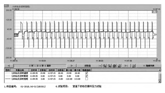
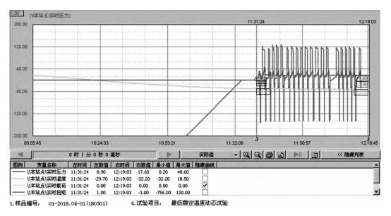
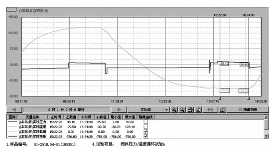
The test system developed by China National Petroleum Corporation Jianghan Machinery Research Institute Co., Ltd. supports a temperature range of -70°C to 360°C, a rated pressure of up to 140 MPa, and a valve switching torque range of 1500 N·m. The system is capable of performing pressure cycling, temperature cycling, and switching cycle tests required for valve products, meeting all test items and requirements specified in Table 1. Figures 1 to 3 present real-time recorded curves from a 34.5 MPa expansion gate valve test conducted by a specific company. The real-time recording curve simultaneously captures data on pressure, temperature, switch status, switch torque, and cycle count, providing an objective representation of the valve's reliability test performance indicators.

Figure 1: Partial curves from the 160-cycle open/close dynamic pressure test at room temperature
Table 1: Reliability Test Items, Methods, and Requirements
|
No. |
Test Item |
Test Method and Requirements |
|
1 |
Dynamic Pressure Test for Open/Close Cycling at Room Temperature |
The downstream end of the valve is filled with the test medium, while the upstream end is pressurized to the rated working pressure. The valve is then opened under full pressure differential and fully closed at a test pressure of ≥50%. |
|
2 |
Low-pressure valve seat test at room temperature |
After closing, the downstream end is pressurized to ≤1% of the test pressure, and the cycle is repeated 160 times. The initial opening torque and rotational torque of the valve should not exceed those specified in the seat test of the valve at room temperature. Apply 5%–10% of the rated working pressure and maintain this pressure for 1 hour. The pressure change observed on the pressure measurement device should be less than 5% of the test pressure or 3.45 MPa, with the smaller value being accepted. |
|
3 |
Dynamic Pressure Test for Open/Close Cycling at the Highest Rated Temperature |
At the highest rated temperature, use gas as the test medium. Fill the downstream end of the valve with the test medium, pressurize the upstream end to the rated working pressure, and open the valve under the full pressure differential. The dynamic opening/closing cycle of the valve should not exceed the specified limit. |
|
4 |
Valve Body and Valve Seat Air Pressure Tests, and Valve Seat Low-Pressure Test at Maximum Rated Temperature |
At the highest rated temperature, apply the corresponding test pressure to the valve body, and maintain the pressure for 1 hour. Similarly, perform the valve seat air pressure test and the valve seat low pressure test, maintaining the pressure for 1 hour in each case. If the pressure change observed on the pressure measurement device is less than 5% of the test pressure or 3.45 MPa, the smaller value shall be accepted. |
|
5 |
Dynamic Air Pressure Test for Open/Close Cycling at Minimum Rated Temperature |
At the lowest rated temperature, use gas as the test medium. Fill the downstream end of the valve with the test medium, pressurize the upstream end to the rated working pressure, and dynamically cycle the valve under the full pressure differential. Close the valve completely at ≥50% of the test pressure. After closing, depressurize the downstream end to ≤1% of the test pressure, and repeat the cycle 20 times. The first and last opening torque, as well as the rotation torque, must not exceed the valve's specified limits. |
|
6 |
Valve Body and Valve Seat Air Pressure Tests, and Valve Seat Low-Pressure Test at Minimum Rated Temperature |
At the lowest rated temperature, apply the corresponding test pressure to both the valve body and valve seat, maintaining the pressure for 1 hour, respectively. If the pressure change observed on the pressure measuring device is less than 5% of the test pressure or 3.45 MPa, the smaller value will be accepted. |
|
7 |
Valve Body Pressure and Temperature Cycle Test |
The valve is partially opened at room temperature, and the pressure is increased to the highest rated temperature with 50% to 100% of the test pressure. The pressure is then maintained at the test pressure for 1 hour. Afterward, when the test pressure reaches 50% to 100% of the valve body pressure/temperature cycle, the pressure is reduced to the lowest temperature and maintained for 1 hour at the test pressure. Once the pressure has been maintained, it is released, and the temperature is raised to room temperature. The pressure is then increased to the highest temperature again, applying the test pressure and maintaining it for 1 hour, after which the pressure is released. Finally, the pressure is reduced to the lowest temperature, the test pressure is applied, and the pressure is maintained for 1 hour before being released and raised to room temperature. If the pressure change during the pressure maintenance period is less than 5% of the test pressure or 3.45 MPa, whichever is smaller, the result will be accepted. |
|
8 |
Valve Body and Valve Seat Pressure Tests, and Valve Body and Valve Seat Low-Pressure Tests at Room Temperature |
At room temperature, apply the corresponding test pressure for the valve body, valve seat, and low pressure test, and maintain the pressure for 1 hour, 15 minutes, 1 hour, and 1 hour, respectively. If the pressure change observed on the pressure measuring device is less than 5% of the test pressure or 3.45 MPa, the smaller value shall be accepted. |
|
9 |
Valve Opening Torque Test at Ambient Temperature |
Apply the rated pressure to the upstream end of the valve and open it under full pressure differential to measure the opening torque. The torque should not exceed the specified limit for the valve. |
|
10 |
Valve Body and Valve Seat Air Pressure Tests, and Valve Seat Low-Pressure Test at Maximum Rated Temperature |
The tested prototype is disassembled and inspected, with relevant items photographed. A written description of any defects, including their degree, is provided. Products and components should be free of design defects and must meet all performance requirements. The inspection includes: a visual examination of the pressure-bearing body and a penetration test of the pressure contact surface between the valve plate and valve seat, with no defects or issues allowed. |

Figure 2: Dynamic air pressure test curve for 20 cycles of opening/closing at the lowest rated temperature
Since the establishment of the reliability test system in 2008, over 40 prototype valve reliability tests have been conducted, with valve diameters ranging from 52 mm to 180 mm, pressures varying from 34.5 MPa to 138.0 MPa, and temperatures spanning from -46°C to 180°C. A wide range of valve models has been rigorously tested. During the initial testing phase, issues frequently arose in the dynamic cycling test or the pressure-holding sealing test.

Figure 3: Pressure/Temperature Cycle Test Curve of Valve Body Under Pressure
After thorough analysis, the prototype’s valve body and bonnet maintained structural integrity and pressure-bearing performance across all tests, meeting reliability requirements. However, the valve stem, stem seal, stem cap, stem pin, ball screw, valve plate, valve seat, and sealing components exhibited varying degrees of issues in multiple tests.
The specific issues observed include: (1) In 160 dynamic tests at room temperature and 20 dynamic tests at high temperature, the valve opening torque exceeded the specified limit. Additionally, the valve stem fractured, the stem pin broke and became stuck, the ball screw was damaged, the valve plate experienced galling and sticking, and both the valve stem sleeve and bonnet showed signs of wear and galling. (2) In the low-temperature dynamic test, significant packing leakage was observed. (3) In sealing tests under various temperature conditions, leakage occurred in the valve stem packing seal, valve cover gasket, and valve plate seal, resulting in a pressure drop exceeding the specified limit.
After analysis, the main causes include: an insufficient and eccentric gap between the valve stem sleeve and the valve cap, leading to strain and increased opening torque; fractures and damage to the valve stem and pin due to material and heat treatment defects, an undersized diameter, excessive clearance, inadequate ball screw reliability, and the inherently high opening torque of the valve. The valve plate and the valve body cavity are not properly matched, and the guide plate is deformed, leading to strain and increased opening torque. Excessive sealing grease in the packing, along with excessive compression, further increases the torque after high-temperature expansion. Some packings and valve seat seals are not resistant to high- and low-temperature cycles, resulting in leakage at low temperatures. After the pressure cycling process, the valve bonnet studs become deformed or are not tightened symmetrically as required, leading to leakage in the gasket ring groove. The geometric accuracy, clearance control, and surface hardness of the valve plate and valve seat were inadequate, leading to strain and leakage on the sealing surface. In response to these issues, after multiple rounds of rectification and optimization, the prototype successfully passed the complete reliability test. Through continuous testing, laboratory researchers and production technicians have gained extensive experience, enhanced design and manufacturing processes, and improved valve reliability. Since 2013, the number of faulty prototypes during testing has significantly decreased, and the root causes of failures can now be accurately identified. The majority of prototypes now successfully pass the reliability test, and the testing duration has been reduced from the initial 13 days to 7-8 days, significantly enhancing product quality and reliability.
Currently, following over 40 reliability tests on valves, to enhance valve reliability, it is essential to strengthen the control over machining and matching dimensions, assembly processes, heat treatment of valve stems and caps, surface spray welding of valve plates and valve seat sealing surfaces, and the selection of non-metallic seals. To address existing issues and verify through reliability testing that the requirements are met, the following specific measures are implemented:
(1) The dimensional accuracy of the valve body’s inner cavity, valve plate, and valve seat, as well as the matching clearance and alignment between the valve stem sleeve and valve cap, must meet specified requirements. Additionally, the chamfer radius on the four longitudinal edges of the valve plate should be improved to prevent interference with the valve body wall during the operational cycle.
(2) The materials for the valve stem and valve stem pin should be carefully selected, and the heat treatment process must be strictly controlled to enhance their mechanical properties and ensure they do not deform or break during normal operation.
(3) The valve stem and valve seat seals are made from Teflon sealing material assemblies to ensure sealing performance under both high and low temperature cycles.
(4) For valves with a rated pressure of 69MPa or higher, the valve plate and valve seat sealing surfaces should be coated with tungsten carbide, achieving a surface hardness of HV1050 or higher to enhance hardness and wear resistance.
(5) When selecting a ball screw for the valve, it must meet the torque requirements and pass both high and low-temperature fatigue cycling tests.
(6) During valve assembly, cleanliness must be maintained, and only a minimal amount of sealing grease should be applied, as excessive grease may interfere with leakage testing. The valve must also meet both the high and low-temperature requirements. The nut should be tightened in strict accordance with the operating procedures, and the valve stem cap should not be overly tightened.
(7) After 160 open/close cycle dynamic pressure tests at room temperature, the valve bonnet studs and the test flange studs at both ends are tightened, inspected, and reinforced in accordance with the valve operation and maintenance manual.
Since 2013, the quality and reliability of wellhead equipment, Christmas trees, and valves that have passed the performance validation testing system have consistently improved, resulting in significant reductions in on-site maintenance costs and time. Through reliability testing, companies have strategically enhanced materials, designs, and processes, improved product quality and technical capabilities, successfully expanded into the Middle East and North Africa markets, and gained recognition from key suppliers. Companies that have passed the PR2 reliability test and received comprehensive reports and certificates have performed well in domestic bidding and procurement, creating a virtuous cycle that supports their expansion and growth. Additionally, the project "Research and Application of the Wellhead Equipment and Christmas Tree Performance Identification Test System" was awarded the second prize for scientific and technological progress by the China Petroleum and Chemical Automation Application Association in July 2018.
A foreign wellhead gate valve, with a diameter of 65mm and a rated pressure of 103.5MPa, has successfully completed 10,000 switching cycle endurance tests after passing the PR2 reliability test. The valve maintained pressures of 103.5MPa and 5.52MPa nitrogen for one hour, with no leakage or visible defects, and is capable of continuing durability testing. In contrast, wellhead valve manufacturers in China still lack comprehensive durability performance data. As the demand for high-reliability valves increases, manufacturers must simulate real-world operating conditions, such as mortar cycle testing, to conduct reliability and durability assessments that meet the stringent demands of harsh environments like shale gas fracturing. In addition, the award-winning project 'Research and Application of Wellhead Equipment and Christmas Tree Performance Identification Test System' received the Second Prize for Scientific and Technological Progress from the China Petroleum and Chemical Automation Application Association in July 2018 (Certificate No. 2017KXJSJ-JB055-2-D01).