
The Working Principle of the Safety Valve (Part Two)
After the overpressure phase, the maximum relief pressure B is reached; return to the re-seat pressure C after the opening and closing pressure difference phase. The safety valve with liquid does not pop suddenly like that with gas (Figure 3), because the flow of the liquid does not generate the expansion force like that of the gas. The safety valve with the liquid must rely on reaction force to reach the opening height.
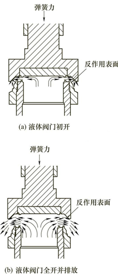
Figure 3 The schematic diagram of the principle of the safety valve with liquid
When the safety valve is closed, the force acting on the valve disc is the same as the force applied to the gas until the force balance is reached, that is, the resultant force that keeps the valve seat closed is close to zero. At the initial opening stage, the overflowing liquid forms a very thin layer of fluid, as shown in Figure 3(a), which rapidly expands between surfaces of valve seats. The liquid impacts the reaction surface of the valve disc's recoil plate, and is deflected downwards, resulting in an upwards reaction force that pushes the valve disc and recoil plate. In the initial 2% to 4% of the overpressure range, these forces usually are formed very slowly.
As the flow gradually increases, the velocity of the liquid flowing through the valve seat also increases. These momentum forces and the resultant force of the acting surface generated by the rapidly released liquid due to the reaction surface being deflected downwards (Figure 3b) are sufficient to make the valve fully open. Under normal circumstances, the valve disc will suddenly rise to a full opening height of 50% to 100% under excess pressure of 2% to 6%. As the excess pressure increases, these forces continue to increase, pushing the valve disc to be fully opened. The discharge volume of the safety valve with liquid should reach the full rated discharge volume under excess pressure of 10% or less according to ASME.
In the process of closing a valve, as the excess pressure decreases, the momentum and reaction of the liquid decrease, and the spring force pushes the valve disc back to be in contact with the valve seat. In the past, many pressure relief valves used for liquid were safety relief valves or relief valves designed for compressible vapor. Many of these valves used for liquid require high excess pressure (25%) to achieve the purposes of full opening and stable operation. This is because the liquid cannot provide the same expansion force as the gas.
ASME Standards of Boilers and Pressure Vessels Chapter Ⅷ requires that the liquid reaches the full opening, stable operation and rated discharge capacity under 10% over pressure, while GB/T 12223-2005 stipulates that the rated discharge pressure should not be more than 1.20 times the set pressure. Figure 4 is the working principle diagram of the pilot-operated safety valve. The pilot-operated safety valve is composed of a main valve and a pilot valve. The pilot valve acts with changes in medium pressure of the system, and the main valve is actuated or controlled by the pilot valve.
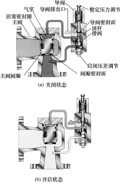
Figure 4 The principle of the pilot-operated safety valve
When the protected system is in normal operating conditions, the pilot valve disc is in a closed state, and the system pressure is transferred from the main valve's inlet to the air chamber above the main valve disc (piston) through the conduit and pilot valve. Because the piston area is larger than the sealing surface area of the valve disc, the system pressure generates a downward force on the valve disc, making the main valve in a closed and sealed state. When the system pressure rises to the set pressure, the pilot valve opens, and at the same time, the slide valve moves upward to close the intake channel of the pilot valve. The medium in the air chamber above the main valve disc is discharged through the opened pilot valve so that the pressure (cavity pressure) above the main valve disc can be reduced, and the main valve disc opens under the push of the inlet pressure to release the pressure of the system. When the system pressure drops to a certain value, the pilot valve will return to its seat and drive the ejector rod to open the slide valve. The system pressure will again enter the air chamber above the main valve disc and push the main valve disc to close through the pilot valve. Figure 5 is the diagram for the pressure relationship of the actual test of the suddenly popped pilot-operated safety valve.
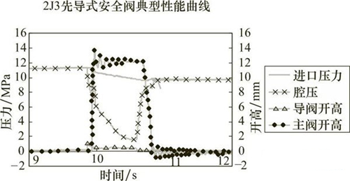
Figure 5 The pressure relationship of the actual test of the suddenly popped pilot safety valve
Figure 3 The schematic diagram of the principle of the safety valve with liquid
When the safety valve is closed, the force acting on the valve disc is the same as the force applied to the gas until the force balance is reached, that is, the resultant force that keeps the valve seat closed is close to zero. At the initial opening stage, the overflowing liquid forms a very thin layer of fluid, as shown in Figure 3(a), which rapidly expands between surfaces of valve seats. The liquid impacts the reaction surface of the valve disc's recoil plate, and is deflected downwards, resulting in an upwards reaction force that pushes the valve disc and recoil plate. In the initial 2% to 4% of the overpressure range, these forces usually are formed very slowly.
As the flow gradually increases, the velocity of the liquid flowing through the valve seat also increases. These momentum forces and the resultant force of the acting surface generated by the rapidly released liquid due to the reaction surface being deflected downwards (Figure 3b) are sufficient to make the valve fully open. Under normal circumstances, the valve disc will suddenly rise to a full opening height of 50% to 100% under excess pressure of 2% to 6%. As the excess pressure increases, these forces continue to increase, pushing the valve disc to be fully opened. The discharge volume of the safety valve with liquid should reach the full rated discharge volume under excess pressure of 10% or less according to ASME.
In the process of closing a valve, as the excess pressure decreases, the momentum and reaction of the liquid decrease, and the spring force pushes the valve disc back to be in contact with the valve seat. In the past, many pressure relief valves used for liquid were safety relief valves or relief valves designed for compressible vapor. Many of these valves used for liquid require high excess pressure (25%) to achieve the purposes of full opening and stable operation. This is because the liquid cannot provide the same expansion force as the gas.
ASME Standards of Boilers and Pressure Vessels Chapter Ⅷ requires that the liquid reaches the full opening, stable operation and rated discharge capacity under 10% over pressure, while GB/T 12223-2005 stipulates that the rated discharge pressure should not be more than 1.20 times the set pressure. Figure 4 is the working principle diagram of the pilot-operated safety valve. The pilot-operated safety valve is composed of a main valve and a pilot valve. The pilot valve acts with changes in medium pressure of the system, and the main valve is actuated or controlled by the pilot valve.
Figure 4 The principle of the pilot-operated safety valve
When the protected system is in normal operating conditions, the pilot valve disc is in a closed state, and the system pressure is transferred from the main valve's inlet to the air chamber above the main valve disc (piston) through the conduit and pilot valve. Because the piston area is larger than the sealing surface area of the valve disc, the system pressure generates a downward force on the valve disc, making the main valve in a closed and sealed state. When the system pressure rises to the set pressure, the pilot valve opens, and at the same time, the slide valve moves upward to close the intake channel of the pilot valve. The medium in the air chamber above the main valve disc is discharged through the opened pilot valve so that the pressure (cavity pressure) above the main valve disc can be reduced, and the main valve disc opens under the push of the inlet pressure to release the pressure of the system. When the system pressure drops to a certain value, the pilot valve will return to its seat and drive the ejector rod to open the slide valve. The system pressure will again enter the air chamber above the main valve disc and push the main valve disc to close through the pilot valve. Figure 5 is the diagram for the pressure relationship of the actual test of the suddenly popped pilot-operated safety valve.
Figure 5 The pressure relationship of the actual test of the suddenly popped pilot safety valve
