
The Working Principle of the Safety Valve (Part One)
A safety valve is a protection device for boilers, pressure vessels, and pressure pipelines. It is used to prevent the pressure in the pressure equipment from exceeding the designed allowable value, thereby protecting the safety of the equipment and its operators. Because the safety valve can operate without relying on any external energy source, it is often used as the last protective device for pressure equipment. In this sense, its function cannot be replaced by other protective devices.
When the pressure of the medium in the pressurized equipment rises abnormally for some reason and reaches the preset value, the safety valve will automatically open and then discharge to prevent the pressure from rising. When the pressure of the medium decreases due to the discharge of the safety valve and reaches another predetermined value, the valve automatically closes to prevent the medium from discharging. When the medium's pressure is at the normal working pressure, the valve remains closed and sealed. The following are examples of common spring direct-loaded safety valves and pilot-operated safety valves for further illustrating the operating principle of safety valves. Figure 1 shows the operating principle of a conventional spring-loaded gas safety valve, and its action is based on the balance of forces. Under normal operating conditions, the inlet pressure is lower than the set pressure; the valve disc is pressed on the valve seat under the action of the spring force, and the valve is in the closed or sealed state. Figure 1(a)
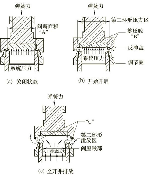
Figure 1 Working principles of gas safety valves
At this time, the spring force F acting on the disc is: F=pA+Fs. P is the pressure of the medium(MPa). A means the pressure area on the disc(mm2). Fs stands for additional force for the downward sealing of the disc and the valve seat (N). The pressing force Fs of the disc on the sealing surface of the valve seat ensures the required sealing. In normal operation, the safety valve is in the closed state, and the upward force of the safety valve disc under the action of the system pressure is less than the downward spring force of the valve disc. The difference value is the additional sealing force Fs, that is, as the system pressure increases, the sealing specific pressure of the safety valve is gradually reduced.
When the inlet pressure of the system is equal to the set pressure of the safety valve, the spring force is equal to the force of the inlet medium acting on the closed disc, and the force between the disc and valve seat is zero. When the inlet pressure is slightly higher than the set pressure, the medium flows through the surface of the valve seat and enters the pressure accumulating chamber "B". As a result of the throttling effect between the recoil plate and regulating ring, the pressure in the pressure accumulating chamber "B" increases (Figure 1b). Because the inlet pressure acts on a larger area at this time, an additional force usually called expansion force is created to overcome the spring force. By adjusting the adjusting ring, the size of the annular flow passage gap can be adjusted to control the pressure in the pressure accumulating chamber "B". At this time, the controlled pressure in the accumulating chamber will overcome the spring force, causing the valve disc to leave the valve seat. The safety valve pops and opens. Once the valve has been opened, additional pressurization will be generated at "C" (Figure 1c). This is caused by the sudden increase in flow and the throttling on an annular flow channel enclosed by the inner edge of the recoil disc's skirt and the outer diameter of the adjusting ring. These additional forces at the "C" part including recoil force will make the valve disc reach a sufficient opening height when it pops.
The flow is always restricted by the opening angle between the valve seat and valve disc until the opening height of the valve disc from the valve seat is close to 1/4 of the throat's diameter. When the valve disc reaches this kind of opening height, the flow is controlled by the area of the throat flow channel instead of that between the valve seat's surfaces. The inlet pressure has fallen below the set pressure so that the spring force can be sufficient to overcome the sum of the three forces of "A", "B", and "C"; the valve closes. Figure 2 shows the set pressure of the valve (A in the figure)
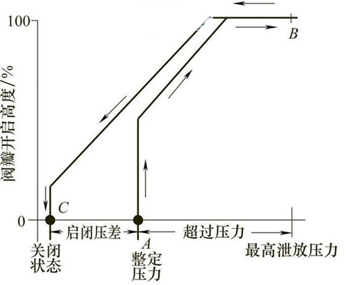
Figure 2 The typical relationship between the opening height of the safety valve disc and the pressure of the protected system
When the pressure of the medium in the pressurized equipment rises abnormally for some reason and reaches the preset value, the safety valve will automatically open and then discharge to prevent the pressure from rising. When the pressure of the medium decreases due to the discharge of the safety valve and reaches another predetermined value, the valve automatically closes to prevent the medium from discharging. When the medium's pressure is at the normal working pressure, the valve remains closed and sealed. The following are examples of common spring direct-loaded safety valves and pilot-operated safety valves for further illustrating the operating principle of safety valves. Figure 1 shows the operating principle of a conventional spring-loaded gas safety valve, and its action is based on the balance of forces. Under normal operating conditions, the inlet pressure is lower than the set pressure; the valve disc is pressed on the valve seat under the action of the spring force, and the valve is in the closed or sealed state. Figure 1(a)
Figure 1 Working principles of gas safety valves
At this time, the spring force F acting on the disc is: F=pA+Fs. P is the pressure of the medium(MPa). A means the pressure area on the disc(mm2). Fs stands for additional force for the downward sealing of the disc and the valve seat (N). The pressing force Fs of the disc on the sealing surface of the valve seat ensures the required sealing. In normal operation, the safety valve is in the closed state, and the upward force of the safety valve disc under the action of the system pressure is less than the downward spring force of the valve disc. The difference value is the additional sealing force Fs, that is, as the system pressure increases, the sealing specific pressure of the safety valve is gradually reduced.
When the inlet pressure of the system is equal to the set pressure of the safety valve, the spring force is equal to the force of the inlet medium acting on the closed disc, and the force between the disc and valve seat is zero. When the inlet pressure is slightly higher than the set pressure, the medium flows through the surface of the valve seat and enters the pressure accumulating chamber "B". As a result of the throttling effect between the recoil plate and regulating ring, the pressure in the pressure accumulating chamber "B" increases (Figure 1b). Because the inlet pressure acts on a larger area at this time, an additional force usually called expansion force is created to overcome the spring force. By adjusting the adjusting ring, the size of the annular flow passage gap can be adjusted to control the pressure in the pressure accumulating chamber "B". At this time, the controlled pressure in the accumulating chamber will overcome the spring force, causing the valve disc to leave the valve seat. The safety valve pops and opens. Once the valve has been opened, additional pressurization will be generated at "C" (Figure 1c). This is caused by the sudden increase in flow and the throttling on an annular flow channel enclosed by the inner edge of the recoil disc's skirt and the outer diameter of the adjusting ring. These additional forces at the "C" part including recoil force will make the valve disc reach a sufficient opening height when it pops.
The flow is always restricted by the opening angle between the valve seat and valve disc until the opening height of the valve disc from the valve seat is close to 1/4 of the throat's diameter. When the valve disc reaches this kind of opening height, the flow is controlled by the area of the throat flow channel instead of that between the valve seat's surfaces. The inlet pressure has fallen below the set pressure so that the spring force can be sufficient to overcome the sum of the three forces of "A", "B", and "C"; the valve closes. Figure 2 shows the set pressure of the valve (A in the figure)
Figure 2 The typical relationship between the opening height of the safety valve disc and the pressure of the protected system
