Abstract: In response to the low efficiency, poor cutting quality, and radiation exposure risks in traditional nuclear valve weld cutting, a novel automatic cutting device has been designed. The device integrates an electric lifting mechanism, gear drive system, connecting rod transmission, and automatic cutting module to achieve high cutting efficiency and precision through coordinated control. In nuclear power systems, valves are essential to operational safety, and their maintenance often involves cutting sealing welds. Traditional tools, including manual cutters and saws, offer low efficiency, uneven quality, and poor adaptability to complex conditions. To overcome these challenges, an intelligent automatic cutting device is designed, with optimized configurations of gears, connecting rods, and other key components. The system enhances cutting quality and efficiency, delivering a reliable solution that ensures both operational safety and economic benefit in nuclear power facilities.
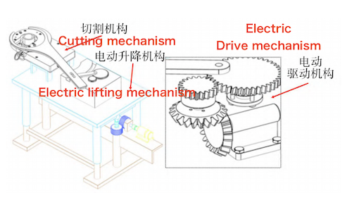
Figure 1 illustrates the overall structure of the automatic cutting device for valve sealing welds. The system comprises an electric lifting mechanism, an electric gear drive, a connecting rod transmission, and an automatic cutting module. The electric lifting module ensures accurate positioning for cutting valve welds at different heights and locations. The bevel gear-driven electric drive module supports heavy loads and high power output, improving stability and minimizing vibration-induced cutting errors. Controlled tool feed is achieved through the connecting rod and cutting module, which rotate a wrench within a set angle using a ratchet mechanism to cut the sealing weld. Cutting accuracy is maintained by adjusting the total thickness and feed per revolution.

Figure 1. Overall Structure
The electric lifting module is first positioned at the valve’s cutting location. The motor then drives the main shaft, and a pair of meshing helical gears changes its direction of motion.Vertical positioning of the platform is accomplished through screw transmission. After positioning, the motor drives the helical gear system mounted on a deep groove ball bearing to deliver power. The large helical gear engages the swing rod through a connecting key, and the swing rod’s end connects to a slider in the guide groove by means of a positioning pin, creating a linkage to the ratchet handle. The ratchet handle executes continuous rotational motion within a specified angle, causing the ratchet disc beneath it to rotate intermittently. Consequently, the cutter attached to the ratchet disc advances and rotates incrementally, allowing for precise cutting of the sealing weld.
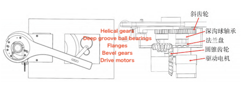
The cutting mechanism (refer to Figure 2) facilitates circular cutting by driving the ratchet handle via the transmission groove on the swing rod. Initially, the safety latch is screwed in and protrudes beyond the ratchet teeth, thereby preventing rotation of the ratchet top plate. Therefore, prior to initiating the cutting process, the safety latch must be retracted to disengage it. Once disengaged, the ratchet top plate is free to rotate, activating the cutting blade to carry out the cutting operation. The torque spring mechanism aligns with the ratchet teeth, allowing the wrench to engage precisely at the weld and rotate clockwise for short-distance cutting.

Figure 2 Cutting Mechanism
When the ratchet wrench advances the cutting device by one tooth pitch, or reaches its maximum rotation angle, it then prepares to return to its starting position. During this counterclockwise return, the torque spring mechanism resets, permitting the wrench to rotate freely and begin the next reciprocating cycle. Rotating the feed bolt causes the tool adjustment block to move forward or backward, which in turn advances or retracts the entire cutting tool, enabling incremental cutting. Similarly, rotating the positioning screw moves the positioning adjustment block forward or backward, which simultaneously adjusts the clamping claws on both sides. This mechanism secures or releases the valve sealing weld area by moving the claws inward to clamp or outward to loosen.
The electric drive mechanism (see Figure 3) employs a bevel gear transmission system, which provides a precise transmission ratio, high efficiency, compact design, reliable operation, and extended service life. The mechanism comprises a servo motor, bevel gear, optical shaft, flange, deep groove ball bearing, hexagonal head bolt, and hexagonal thin nut. The bevel gear is specified as 20×1.5, while the deep groove ball bearing meets the GB/T 276—1994 standard (model 62800-2Z). The bevel gear transmits motion through the flange and deep groove ball bearing—both fixed to the housing—and drives the swing rod into continuous rotation via a pin hole on the gear.
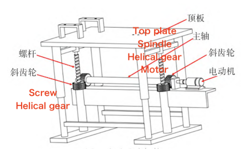
Figure 4 illustrates the electric lifting mechanism, which comprises a 42HS48-0100 motor, base frame, top plate, main shaft, helical gears, lead screws, and additional components. The motor rotates the main shaft, whose two helical gears engage corresponding gears beneath the top plate, subsequently driving the lead screws. As the gears on the main shaft rotate, they drive the gears beneath the top plate, which in turn rotate the screws, resulting in the platform rising. When the motor rotates forward, it drives the main shaft to rotate clockwise through the coupling, causing the cutting platform to rise. Conversely, when the motor reverses, the main shaft rotates counterclockwise, lowering the platform.

Figure 3 Electric Drive Mechanism

Figure 4 Electric Lifting Mechanism
Besides the core systems—the cutting mechanism, electric drive mechanism, and electric lifting mechanism—several auxiliary components have been incorporated to improve safety and performance. A distance sensor mounted on the tool adjustment block monitors the safe distance between the cutting tool and the weld. Additionally, it detects whether the tool has fully retracted from the cutting area, thereby protecting the tool from potential damage. Additionally, a small fan is installed on the ratchet top plate to provide timely cooling of the tool and weld chips under high-temperature conditions. This cooling not only prevents heat-induced cutting problems but also assists in clearing weld debris from the cutting surface, thereby enhancing overall cutting quality.
The control system employs the Siemens S7-300 series PLC as its central controller. The touch screen functions as the human-machine interface (HMI), enabling two-way communication with the PLC for real-time monitoring and control. The servo motors for the automatic lifting mechanism, electric drive mechanism, and cutting device feed screw are controlled through the PLC control panel. Operators utilize the touch screen to input processing parameters and precisely manage the operation of each component. The PLC and servo system work in coordination to control actuator movement, with encoders mounted on each servo motor shaft ensuring precise positioning. This setup improves operational efficiency and lowers overall system costs.
While programming instructions for PLCs are generally consistent across devices, variations in design processes, control functions, and loop requirements lead to unique implementations for each system. The control process for this device is as follows: when the lifting platform reaches the designated cutting area, the lifting servo motor control module issues a stop command. The operator then manually tightens the expansion screw to clamp the valve pipeline. Next, the servo motor is commanded to initiate cutting, driving the bevel gear to rotate and causing the ratchet handle to execute a reciprocating motion, thereby commencing the cutting operation. Once the desired cutting depth is reached and the ratchet handle returns to its starting position, the feed screw servo motor receives a retract command. After retraction is complete, the PLC issues stop commands to all subsystems. The entire cutting process can be operated by the user via physical buttons or the touch screen interface. A control flowchart of the cutting device is provided to illustrate this sequence.
The human-machine interface (HMI) of the cutting device primarily comprises two components: the control panel and the touch screen. The control panel contains essential elements such as the main power switch, automatic/manual mode selector, and emergency stop button. Additionally, it integrates various sensors, actuators, and control algorithms to facilitate precise and automated control of the cutting process. The touch screen enables operators to input processing parameters tailored to specific cutting requirements. These parameters include the lifting height of the platform, the output power and spindle speed of the servo motor in the drive mechanism, and the output power and spindle speed of the servo motor controlling the feed screw. Each subsystem’s operational status is shown in real time on the touch screen, with automatic alarm notifications prompting prompt operator response in case of errors.
To tackle the existing challenges of low efficiency, inconsistent cutting quality, and limited operational safety in processing nuclear power valve sealing welds, this paper introduces the design of a novel automatic cutting device. This paper details the working principles of the device’s key mechanical structures and control system. The proposed solution provides an efficient, precise, and safe method for cutting sealing welds in nuclear power valves, thereby enhancing maintenance practices and operational reliability within the nuclear industry.