
Quick Lifting Metal Seated Plug Valves
The working principle, structural features and product performance of the quick lift metal seated plug valve are introduced, and the fast transmission systems are composed of hydraulic actuators through racks, gears and multi-thread threads.
1. Overview
The fast-lifting metal seated plug valve is mainly used for venting pipelines of offshore oil drilling platforms. The working condition is that the system pressure difference is great and the medium scours much. It is considered that the metal-seated plug valve is the best choice. The nominal diameter of the valve is DN300; the nominal pressure is Class 600, and the opening and closing time of the valve is less than 0.3 seconds.
2. Structural features
2.1. Lifting and rotating mechanism
The friction resistance is very great when the cock is directly rotated at an angle of 90 to open the valve due to the big contact area between the valve body and the sealing pair of the cock, and the conical arc surface. Therefore, the metal seated cock valve generally has the design of lifting first and then rotating. The lifting and rotating mechanism has 2 handles (handwheels). First, rotate the handwheel to lift the cock, so that the sealing surface of the cock and the valve body is separated, and then operate the handle to rotate the cock at an angle of 90 to open the valve (Figure 1). This kind of driving mechanism has a complex structure, and it is more troublesome to operate if electric, pneumatic or hydraulic actuators are used.
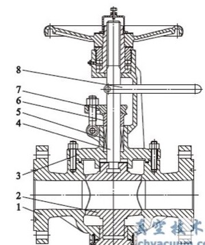
Figure 1 Lifting metal seated plug valves
The fast-lifting metal seated plug valve (Figure 2) has a simple structure of lifting and rotating the plug once. A track pin is installed in the middle of the valve stem, and a needle roller bearing is installed at both ends of the pin to roll in the guide groove of the bracket. Therefore, the movement of the valve stem is limited by the guide groove of the bracket. The guide grooves of the bracket are symmetrically distributed on both sides of the bracket, each of which is processed with a straight groove and a rotated spiral groove with an angle of 90. When the valve stem is moving up and down, it is limited by the track pin and the needle bearing. The valve stem first rises along the straight groove, and then rotates at an angle of 90 along the spiral groove. The valve stem and the cock are connected through a T-shaped groove, and they move synchronously, so that the cock can be lifted first and then rotated and the cock can be opened with less effort.
2.2. Support seats
Support seats are designed on the upper and lower ends of the cock. The upper and lower support seats can transmit the radial force of the medium acting on the cock to the upper and lower parts of the valve body. The inner hole (guide hole) of the support seat has circumferential and axial friction with the upper and lower guide shafts of the cock. The friction force is small due to the small size of the inner hole of the support seat, which reduces the opening and closing torque of the valve.
2.3. Quick operating mechanism
According to the working conditions, the system requires the opening and closing time of the valve to be less than 0.3s, which is difficult to achieve according to the usual mechanical hydraulic transmission. The fast-lifting metal seated plug valve adopts a fast hydraulic cylinder and multi-line short-tooth trapezoidal thread transmission.
Calculate the distance that the valve stem drives the cock to rise vertically when the valve is opened. This distance is composed of three parts. ① When the cock is lifted, its sealing surface is separated from the sealing surface of the valve body, and the radial gap between the two is about 1.7mm. The vertical rising distance of the cock should be 20mm. ② The median diameter of the guide helical groove of the bracket is 85mm. After calculation, the straight-up distance of the valve stem when it rotates at an angle of 90 is 25mm. ③ The top of the spiral guide groove has a section of the straight groove. To stabilize the valve stem and improve the anti-vibration effect, the needle bearing should also rise into the straight groove about 5mm to realize the full opening of the valve.
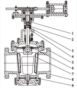
Figure 2 Quick lift metal seated plug valves
1. Overview
The fast-lifting metal seated plug valve is mainly used for venting pipelines of offshore oil drilling platforms. The working condition is that the system pressure difference is great and the medium scours much. It is considered that the metal-seated plug valve is the best choice. The nominal diameter of the valve is DN300; the nominal pressure is Class 600, and the opening and closing time of the valve is less than 0.3 seconds.
2. Structural features
2.1. Lifting and rotating mechanism
The friction resistance is very great when the cock is directly rotated at an angle of 90 to open the valve due to the big contact area between the valve body and the sealing pair of the cock, and the conical arc surface. Therefore, the metal seated cock valve generally has the design of lifting first and then rotating. The lifting and rotating mechanism has 2 handles (handwheels). First, rotate the handwheel to lift the cock, so that the sealing surface of the cock and the valve body is separated, and then operate the handle to rotate the cock at an angle of 90 to open the valve (Figure 1). This kind of driving mechanism has a complex structure, and it is more troublesome to operate if electric, pneumatic or hydraulic actuators are used.
Figure 1 Lifting metal seated plug valves
The fast-lifting metal seated plug valve (Figure 2) has a simple structure of lifting and rotating the plug once. A track pin is installed in the middle of the valve stem, and a needle roller bearing is installed at both ends of the pin to roll in the guide groove of the bracket. Therefore, the movement of the valve stem is limited by the guide groove of the bracket. The guide grooves of the bracket are symmetrically distributed on both sides of the bracket, each of which is processed with a straight groove and a rotated spiral groove with an angle of 90. When the valve stem is moving up and down, it is limited by the track pin and the needle bearing. The valve stem first rises along the straight groove, and then rotates at an angle of 90 along the spiral groove. The valve stem and the cock are connected through a T-shaped groove, and they move synchronously, so that the cock can be lifted first and then rotated and the cock can be opened with less effort.
2.2. Support seats
Support seats are designed on the upper and lower ends of the cock. The upper and lower support seats can transmit the radial force of the medium acting on the cock to the upper and lower parts of the valve body. The inner hole (guide hole) of the support seat has circumferential and axial friction with the upper and lower guide shafts of the cock. The friction force is small due to the small size of the inner hole of the support seat, which reduces the opening and closing torque of the valve.
2.3. Quick operating mechanism
According to the working conditions, the system requires the opening and closing time of the valve to be less than 0.3s, which is difficult to achieve according to the usual mechanical hydraulic transmission. The fast-lifting metal seated plug valve adopts a fast hydraulic cylinder and multi-line short-tooth trapezoidal thread transmission.
Calculate the distance that the valve stem drives the cock to rise vertically when the valve is opened. This distance is composed of three parts. ① When the cock is lifted, its sealing surface is separated from the sealing surface of the valve body, and the radial gap between the two is about 1.7mm. The vertical rising distance of the cock should be 20mm. ② The median diameter of the guide helical groove of the bracket is 85mm. After calculation, the straight-up distance of the valve stem when it rotates at an angle of 90 is 25mm. ③ The top of the spiral guide groove has a section of the straight groove. To stabilize the valve stem and improve the anti-vibration effect, the needle bearing should also rise into the straight groove about 5mm to realize the full opening of the valve.
Figure 2 Quick lift metal seated plug valves
1. Valve stems 2. Track pins 3. Shock columns 4. Stands 5. Valve bonnets 6. Upper support seats 7. Cocks 8. Valve bodies 9. Lower support seats
From the closed state to the full opening of the valve, the vertical rise distance of the valve stem is 50mm, that is, the hydraulic drive mechanism makes the valve stem rise linearly within 0.3s to a distance of 50mm. To make the valve complete the action within 0.28s, the inner diameter of the power source (the drive cylinder) is 200mm; the oil pressure is 22MPa, and the thrust generated is 690kN, which can meet the force required for the opening of the cock.
The modulus of the rack and pinion of the hydraulic drive mechanism is 3mm. The number of teeth of the gear is 17; the gear rotates one circle, and the stroke of the rack is 53.38mm. The gear and the valve stem nut are fixed as a whole. When the gear rotates one circle, the valve stem nut rotates one circle at the same time. The valve stem nut will drive the valve stem to move up and down. The valve stem adopts short-tooth trapezoidal thread (DIN380), with high-strength tooth root and great axial force transmission. The valve stem thread design is DTr60 × 54 (P9) (6 short pitch trapezoidal threads). When the stem nut turns 1 circle, the axial stroke of the stem is 54mm. When the valve is opened, the axial stroke of the valve stem is 50mm, so the gear or the stem nut only needs to rotate 1 circle within 0.28s. To ensure that the gear rotates one circle within 0.28s, the rack (the piston in the cylinder) is required to move 53.38mm within 0.28s. It can be seen from the calculation that the oil inlet volume of the oil cylinder is 1.68L within 0.28s, and the rated flow rate of the solenoid valve of the oil inlet pipe should be greater than 360L/min. At present, the rated flow rate of the largest high-pressure hydraulic control solenoid valve provided in the market is 100L/min, so 4 solenoid valves should be installed on the oil cylinder, that is, 4 ZG1/2 high-pressure pipe joints should be installed at the inlet and outlet.
2.4. Buffer and vibration reduction mechanism
In order to prevent the impact vibration caused by the action of the fast operating mechanism, in addition to the throttling and buffering of the oil cylinder piston, a cylindrical rubber damping and shock-absorbing column (Figure 3) is designed at the lower end of the spiral guide groove of the bracket, which not only reduces noise, but also can prevent damage to transmission parts due to impact.
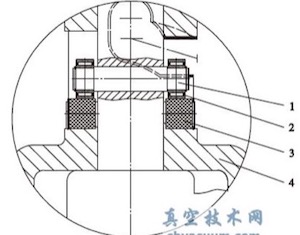
1. Track pins 2. Needle bearing 3. Shock column 4. Stands
Figure 3 Buffer and vibration reduction structure
3. Conclusion
The quick-lifting metal seated plug valve is not only suitable for high-pressure differential conditions, but also meets the functional requirements of quick opening and closing shut-off valves, and will play an important role in offshore oil drilling platforms.
3. Conclusion
The quick-lifting metal seated plug valve is not only suitable for high-pressure differential conditions, but also meets the functional requirements of quick opening and closing shut-off valves, and will play an important role in offshore oil drilling platforms.
