
Analysis and Measures of Internal Leakages of Globe Valves (Part two)
4. Measures for avoiding internal leakages
For small-diameter forged steel globe valves with a size less than and equal to DN50, the integrated forging process is adopted for the connection between the valve stem and the valve disc instead of the trapezoidal end (Figure 6). This method eliminates the gap between the valve handle and the valve stem, reducing the inclination of the valve disc and achieving the purpose of reliable sealing.
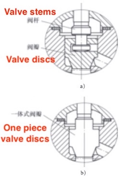
Figure 6 Two connection methods of valves
a) Trapezoidal end with connection b) Integral forging and forming
According to the regulations of API 623, the sealing surface of the valve seat can be designed with a circular arc sealing surface (Figure 7), and the seal between valve discs and valve seats is a line seal. Assuming that after the globe valve is installed vertically, there is an inclination angle of a° between the axis of the valve disc and the sealing cone surface of the valve seat, and the axis deviation is L. When the valve stem pushes the valve seat close to the seat, a small part of the arc’s sealing surface of the valve seat will first touch the sealing surface of the valve seat. Under the continuous push of the valve stem, the circular arc sealing surface of the valve seat will tend to self-align and seal. Finally, the valve seat will be well attached to the sealing surface of the valve seat to ensure reliable sealing.
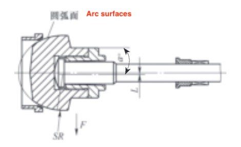
Figure 7 Discs with arc sealing surfaces
When designing a globe valve with a size of DN300, the guide design of the valve disc can be adopted (Figure 8). The guide can make the axis of the sealing surface of the disc always coincide with that of the valve seat to avoid the sealing not fitted.
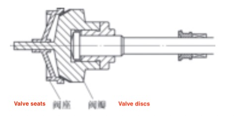
Figure 8 Discs with guide
3. Internal leakages caused by the improper selection of manual devices
1. A brief description of internal leakage
When the medium of the globe valve flows from bottom to top, the medium force needs to be overcome for the seal of the globe valve, the friction of the packing, and the necessary specific pressure of the medium seal should be provided. In this case, the globe valve needs to provide a great axial force to achieve sealing. After the on-site workers turn the hand wheel or the hand wheel of the gearbox to close the valve, the valve is not closed well, and leakage occurs; the lever tool can be used to turn the handwheel again to seal the valve.
2. The analysis of the causes of internal leakages
Handwheels or gearboxes is not properly selected, and proper sealing is not provided.
3. Measures for avoiding internal leakages
The small diameter handwheel drives the valve, and the conventional handwheel can be replaced with an impact handwheel. The handwheel with the same diameter can increase the force of the rim of the handwheel by many times by the kinetic energy of the impact handwheel, thus providing a greater axial sealing force for valve stems.
The globe valve with handwheel driven lifting stems can be equipped with a plane thrust bearing (GBT301-2015), thrust needle roller bearing (GB/T 4605-2003) and self-lubricating sliding bearing to reduce the friction torque between the stem nut and the bracket, increasing transmission efficiency.
For valves with large-diameter gearboxes, a multi-stage reduction mechanism can be selected to provide greater output torque by increasing the transmission speed ratio of the gearbox. The double or triple thread is used for the corresponding valve stem thread, which increases the thread lead and reduces the opening and closing time of the valve.
4. Internal leakages caused by inaccurate positioning of electric and pneumatic devices
1. A brief description of internal leakage
Both electric and pneumatic devices are equipped with limit mechanisms. Usually, when debugging the device, the technicians will limit the closing position of the valve through empirical judgment, and then perform the sealing and pressure test after the limit to achieve the standard sealing performance. However, in actual engineering applications, the internal leakage still often happens for the valve.
2. The analysis of the causes of internal leakages
The debugging of the driving device is performed in the normal temperature environment. In actual working conditions, the temperature change will cause the valve to have a certain amount of deformation, which will lead to the problem that the previous limit position cannot guarantee the seal.
3. Measures for avoiding internal leakages
The driving device can be debugged again on site, and the valve can be closed with the manual device on the driving device to ensure that the valve does not leak, and then set a new limit point.
When the medium temperature is not too high, the metal seated valve can be replaced with a non-metal seated valve (Figure 9), because the non-metal seated material can continue to provide sealing force in the case of a slight deformation.
Figure 9 The sealing of the globe valve
a) metal seated valves b) non-metal seated valves
5. Conclusion
The leakage of globe valves encountered in previous engineering applications is summarized and analyzed. The cause of internal leakages of globe valves in the case of non-general damage is judged. After improvement, there is good feedback on the optimized valve.
For small-diameter forged steel globe valves with a size less than and equal to DN50, the integrated forging process is adopted for the connection between the valve stem and the valve disc instead of the trapezoidal end (Figure 6). This method eliminates the gap between the valve handle and the valve stem, reducing the inclination of the valve disc and achieving the purpose of reliable sealing.
Figure 6 Two connection methods of valves
a) Trapezoidal end with connection b) Integral forging and forming
According to the regulations of API 623, the sealing surface of the valve seat can be designed with a circular arc sealing surface (Figure 7), and the seal between valve discs and valve seats is a line seal. Assuming that after the globe valve is installed vertically, there is an inclination angle of a° between the axis of the valve disc and the sealing cone surface of the valve seat, and the axis deviation is L. When the valve stem pushes the valve seat close to the seat, a small part of the arc’s sealing surface of the valve seat will first touch the sealing surface of the valve seat. Under the continuous push of the valve stem, the circular arc sealing surface of the valve seat will tend to self-align and seal. Finally, the valve seat will be well attached to the sealing surface of the valve seat to ensure reliable sealing.
Figure 7 Discs with arc sealing surfaces
When designing a globe valve with a size of DN300, the guide design of the valve disc can be adopted (Figure 8). The guide can make the axis of the sealing surface of the disc always coincide with that of the valve seat to avoid the sealing not fitted.
Figure 8 Discs with guide
3. Internal leakages caused by the improper selection of manual devices
1. A brief description of internal leakage
When the medium of the globe valve flows from bottom to top, the medium force needs to be overcome for the seal of the globe valve, the friction of the packing, and the necessary specific pressure of the medium seal should be provided. In this case, the globe valve needs to provide a great axial force to achieve sealing. After the on-site workers turn the hand wheel or the hand wheel of the gearbox to close the valve, the valve is not closed well, and leakage occurs; the lever tool can be used to turn the handwheel again to seal the valve.
2. The analysis of the causes of internal leakages
Handwheels or gearboxes is not properly selected, and proper sealing is not provided.
3. Measures for avoiding internal leakages
The small diameter handwheel drives the valve, and the conventional handwheel can be replaced with an impact handwheel. The handwheel with the same diameter can increase the force of the rim of the handwheel by many times by the kinetic energy of the impact handwheel, thus providing a greater axial sealing force for valve stems.
The globe valve with handwheel driven lifting stems can be equipped with a plane thrust bearing (GBT301-2015), thrust needle roller bearing (GB/T 4605-2003) and self-lubricating sliding bearing to reduce the friction torque between the stem nut and the bracket, increasing transmission efficiency.
For valves with large-diameter gearboxes, a multi-stage reduction mechanism can be selected to provide greater output torque by increasing the transmission speed ratio of the gearbox. The double or triple thread is used for the corresponding valve stem thread, which increases the thread lead and reduces the opening and closing time of the valve.
4. Internal leakages caused by inaccurate positioning of electric and pneumatic devices
1. A brief description of internal leakage
Both electric and pneumatic devices are equipped with limit mechanisms. Usually, when debugging the device, the technicians will limit the closing position of the valve through empirical judgment, and then perform the sealing and pressure test after the limit to achieve the standard sealing performance. However, in actual engineering applications, the internal leakage still often happens for the valve.
2. The analysis of the causes of internal leakages
The debugging of the driving device is performed in the normal temperature environment. In actual working conditions, the temperature change will cause the valve to have a certain amount of deformation, which will lead to the problem that the previous limit position cannot guarantee the seal.
3. Measures for avoiding internal leakages
The driving device can be debugged again on site, and the valve can be closed with the manual device on the driving device to ensure that the valve does not leak, and then set a new limit point.
When the medium temperature is not too high, the metal seated valve can be replaced with a non-metal seated valve (Figure 9), because the non-metal seated material can continue to provide sealing force in the case of a slight deformation.
Figure 9 The sealing of the globe valve
a) metal seated valves b) non-metal seated valves
5. Conclusion
The leakage of globe valves encountered in previous engineering applications is summarized and analyzed. The cause of internal leakages of globe valves in the case of non-general damage is judged. After improvement, there is good feedback on the optimized valve.
