Orbital plug valves are commonly used in industrial applications to control the flow of liquids and gases. These valves feature a cylindrical plug that rotates within the valve body to regulate fluid flow through the system. The unique design of orbital plug valves allows for precise control of flow rates and pressure levels, making them ideal for processes where accuracy is critical. One key advantage of orbital plug valves is their ability to provide bubble-tight shutoff, ensuring zero leakage when the plug valve is closed. This makes them especially suitable for applications where safety and environmental protection are paramount.
After decades of continuous technological advancement, orbital plug valves have proven to be safe and reliable. They entered the Chinese market in the 1980s and have since been widely used in civil aviation airports and aprons. Structurally, orbital plug valves fall under the category of expansion cylindrical plug valves. However, due to their unique design, they differ in certain aspects from standard expansion plug valves and are therefore introduced separately below.
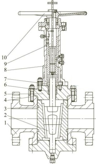
Figure 1. Orbital Plug Valve
1. Valve body 2. Plug 3. Sealing ring 4. Gasket 5. Valve bonnet 6. Packing 7. Gland 8. Bracket 9. Valve stem 10. Hand wheel
The seal (slider) of the orbital plug valve is connected to the plug (cock) via a guide rail structure. During valve opening, the plug is first raised to a specific height, as determined by the design, using the transmission mechanism. As it rises, the two sliders are gradually drawn inward toward the center of the valve by the plug. Once the sealing surfaces of the sliders are completely separated from the valve body and a designated gap is formed, the transmission mechanism continues to rotate the plug and sliders together by 90°, fully opening the valve. During the closing process, the transmission mechanism first rotates the plug and sliders 90° together (putting the valve in a closed position, though not yet sealed). It then pushes the plug downward. As the plug descends, the sliders are driven outward toward the sealing surfaces on both sides of the valve body. When the elastic sealing rings on the sliders are evenly compressed against the valve body’s sealing surfaces, a tight seal is formed.
Orbital plug valves are primarily used in metering systems, metering calibration systems, multi-branch blending and distribution systems, tank bottom isolation, aviation fuel storage and transportation, airport refueling hydrant systems, and high-frequency loading and unloading operations. Typical media include aviation kerosene, light oil, natural gas, liquefied petroleum gas, pipeline gas, and other similar substances. These valves are ideal for providing reliable shutoff in such applications.
Orbital plug valves with a double-sealing structure at the middle flange are commonly used for media such as aviation kerosene, natural gas, liquefied petroleum gas, and refined oil. Since substances like aviation kerosene are highly permeable, flammable, and explosive, a dual-sealing system—consisting of an O-ring and a spiral wound gasket—is employed at the middle flange to prevent any leakage (Figure 2).
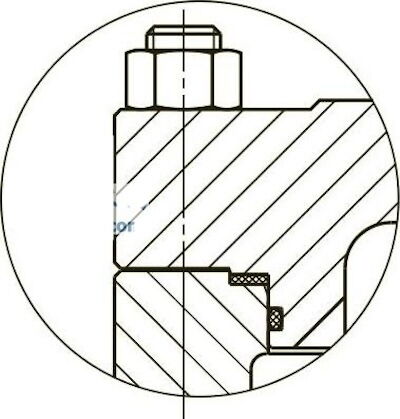
Figure 2. Middle flange double-sealing structure
During operation, the valve core of an orbital plug valve must perform both vertical (up-and-down) and rotational movements. Given the complexity of these motions and the specific characteristics of the media involved, a combination seal using both internal and external O-rings along with traditional packing is adopted to ensure safety and sealing reliability (Figure 3).
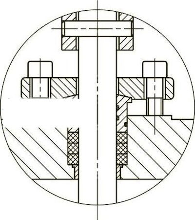
Figure 3. Combined sealing structure with internal and external O-rings and packing
In accordance with API 6D, all double-sealed valves must be equipped with an overpressure relief device and function. The pressure differential requiring relief is typically caused by changes in ambient temperature. When a double-sealed valve is closed, the medium trapped in the valve’s middle cavity may expand due to rising ambient temperatures, resulting in a gradual increase in pressure. If this pressure is not relieved in a timely manner, it can seriously affect valve operation and may even cause structural damage, such as valve expansion or cracking, posing significant safety risks to the system.
Orbital plug valves generally employ three types of pressure relief systems:
a. Manual Pressure Relief System (used for manually operated valves)
This system typically uses a needle valve installed on the valve body, as shown in Figure 4(a). When the valve is closed, the cavity pressure relief valve is opened to release the medium trapped in the middle cavity, either upstream into the pipeline or to the atmosphere. When discharging to the atmosphere, the sealing performance of the valve can also be tested.
b. Differential Pressure Relief System (used for both manual and electric valve operation)
This system consists of a piping assembly incorporating a check valve, as shown in Figure 4(b). The system includes a manual relief valve, a tee connector, a check valve, and an isolation valve. The isolation valve is normally kept open. When the valve is closed, overpressure in the middle cavity is relieved via the check valve to the upstream side of the pipeline. Opening the manual relief valve simultaneously allows testing of the valve’s sealing performance. The manual relief valve must be closed before the valve is opened.
c. Automatic Pressure Relief System (used for electrically operated valves)
When the valve is closed, the pressure relief valve is automatically activated by the actuator mechanism, allowing the valve cavity to vent to the upstream pipeline or externally, as required.
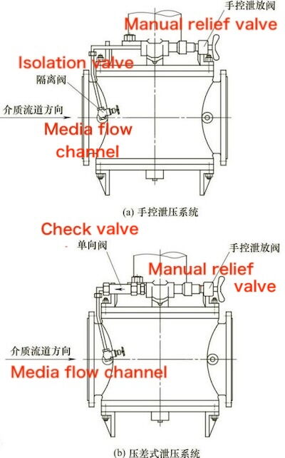
(a) Manual pressure relief system (b) Differential pressure relief system
Figure 4 Pressure relief system of rail plug valves
The operating mechanism of the valve and the thread sleeve mechanism of the self-locking orbital plug valve adopt a unique L-shaped groove structure, as shown in Figure 5(a). This design separates the axial linear movement from the 90° rotational movement of the plug, resulting in smooth and effortless valve operation. In Figure 5(a), A-B represents the linear motion segment, B-C the 90° rotational segment, and the guide key slides within the groove. To reduce the number of handwheel rotations, the trapezoidal threads on the valve stem and threaded sleeve generally feature double or multiple starts. The gear transmission mechanism is inherently self-locking, and the trapezoidal thread used is a heavy-duty type capable of withstanding greater loads.
Among similar valves currently on the market, the guide groove is sometimes designed in a V shape, as shown in Figure 5(b). This groove forms a nearly V-shaped spiral on the cylindrical surface of the screw sleeve. Its operating principle is as follows: A-B represents the initial linear motion stage of the cock; B-C involves both linear and rotational movements, during which the guide key experiences higher shear forces, demanding greater strength. Additionally, the plug must be designed with a longer stroke to prevent excessive friction between the soft sealing surface and the valve body sealing surface. Failure to do so increases operating torque and shortens valve service life. For these reasons, the V-shaped guide groove structure has critical design drawbacks.
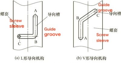
(a) L-shaped guide mechanism (b) V-shaped guide mechanism
Figure 5 Guide groove structure
After precision machining (grinding), the internal cavity of the valve body is hard chrome plated to enhance its resistance to corrosion, erosion, wear, and rust. The slider is also hard chrome plated after machining and before the fluororubber is applied, ensuring the durability and corrosion resistance of its metal sealing surface. The plug, together with the upper and lower shafts, is nickel plated after machining to provide excellent protection against rust and corrosion.
The valve stem undergoes quenching and tempering after rough machining. Following fine machining, it is nitrided to achieve a surface hardness of no less than 900 HV, thereby improving its resistance to galling and wear, especially in the threaded sleeve. The L-shaped guide groove and the guide key head on the threaded sleeve are both machined and quenched to a hardness of no less than 45 HRC, significantly enhancing wear resistance and ensuring smooth sliding of the guide key within the groove.
The orbital plug valve is equipped with windows on both sides of the bracket, allowing for online adjustment and maintenance of the packing. In the event of packing leakage, additional packing can be added or the existing packing can be replaced without removing the valve from service.
The plug of the orbital plug valve features an integral casting design, with the upper and lower shafts cast as a single unit. This ensures that the shafts possess sufficient rigidity, strength, and resistance to bending when subjected to unidirectional pressure. The upper and lower shafts are supported by the valve bonnet and bottom bonnet, respectively, with bearings used to ensure accurate alignment. The machining precision and hardness of the bearings help prevent friction and wear between the shafts and bearings caused by medium pressure, thereby reducing overall friction.
Orbital plug valves are designed for low-torque operation. Bearings on the upper and lower shafts of the plug ensure precise alignment and minimize friction between the plug and the bottom bonnet. This is particularly important for large-diameter valves, where the slider's movement during rotation can generate significant friction, leading to high operating torque. Prolonged friction between the slider and the bottom bonnet can result in wear (wear marks), which may eventually hinder the slider's movement. To resolve this issue, a tungsten carbide-coated bearing ring with a hardness greater than 65 HRC is installed on the bottom cover, while a hardened ball with a hardness above 60 HRC is positioned at the base of the slider. The combination of precision machining and high material hardness effectively prevents operational failures and ensures smooth, effortless valve operation.