Abstract: Electric rising stem flat-bottom gate valves are widely used in municipal pipeline systems for raw water, potable water, and sewage applications. Municipal pipelines play a critical role in delivering tap water to households, making flat-bottom gate valves an indispensable component of the system. Large-diameter (DN1200 and above) soft seated flat-bottom gate valves, in particular, fill a domestic market gap for large shut-off valves. Featuring a compact installation length and low cost, these valves demand advanced manufacturing processes and strict quality control to ensure reliable performance. To ensure product reliability, this study examines the materials and manufacturing processes of these valves, identifies key production challenges, and proposes targeted solutions to improve inspection pass rates, enhance market competitiveness, and promote their widespread application in municipal pipeline systems.
Currently, flat-bottom gate valves available on the market are prone to serious sediment buildup, as debris tends to accumulate in the valve cavity and hinder proper closure. Wedge-type soft seated flat-bottom gate valves, by contrast, are designed to resist fouling. Owing to their combined advantages—reliable sealing performance, simple manufacturing, and cost-effectiveness—they have been widely adopted over the past decade, particularly in water supply systems, where they have largely replaced traditional hard-seated gate valves. The parallel single-disc gate valve, a type of single-disc valve, derives its name from the parallel arrangement of its gate sealing surfaces and the seat sealing surfaces that are perpendicular to the pipeline centerline. However, in large-diameter wedge-type soft-seated gate valves (≥DN1200), the dimensional tolerances of the castings and the precision of the surface finish often make it difficult for the gate caulking to meet design specifications. This often results in sealing failures and a high rate of rework and scrap, a challenge that valve manufacturers find difficult to resolve. Furthermore, the overall caulking cost for large-diameter gates is relatively high. To address these issues, this study proposes a scale-resistant, soft-seated flat-bottom gate valve. When fully open, the gate creates a full-bore passage with low flow resistance, minimal water loss, and excellent resistance to bottom scaling. These valves are widely used in municipal water supply and sewage networks. The electric rising-stem flat-bottom gate valve integrates a scale-resistant, soft-seated flat gate with a rising stem and an electric actuator. The valve assembly comprises the valve body, gate, locking screw, wedge-shaped top block, sealing ring, valve shaft, bonnet, bracket, actuator, return spring, anti-debris tray, and guide block. Compared to existing designs, this valve provides several advantages, including a shorter construction length, smaller installation footprint, higher test pass rates, bidirectional pressure resistance, lower cost, and shorter production cycles. In recent years, numerous studies have focused on optimizing gate valve designs. For instance, Zhao Jiayi et al. refined the dimensions of the gate guide rail to meet stress requirements and minimize wear. Wu Binbin et al. addressed structural issues such as gate disc cracking, drive chain disassembly difficulties, and sealing surface damage in main shut-off valves for gas supply systems.
Lin Sunrong et al. integrated experimental research with finite element simulations to improve the sealing performance of DN300–900LB parallel gate valves. Zhou Xingbiao et al. improved guide plate design, converting the gate disc’s mechanical behavior from a cantilever to a simply supported beam, thus reducing internal leakage caused by disc warping and sealing surface damage. However, research specifically addressing gate valve manufacturing processes remains limited. This study focuses on the critical challenges in production, aiming to improve inspection pass rates, reduce manufacturing costs, and enhance market competitiveness.
Rising-stem flat-bottom gate valves are soft-seated, flat-plate valves. They can be classified by operation mode as either electric or manual and by structure as non-rising stem or rising-stem flat-bottom gate valves. Figure 1 illustrates a rising-stem flat-bottom gate valve, consisting of the valve body and a flat-plate gate assembly. A single gate typically functions as the primary closing element. Mechanical force or system pressure pushes the gate seal against the valve seat, improving sealing performance. Flat-bottom gate valves control media flow by raising or lowering the gate vertically. During opening, the actuator—manual, electric, or hydraulic—moves the valve stem upward, guiding the gate along the vertical groove. When the gate is fully lifted off the valve seat, the flow cross-section is maximized, minimizing pressure drop. Manufacturing large-diameter flat-bottom gate valves places significant demands on equipment. Typically, the production process requires:
- A double-column vertical lathe with a maximum machining diameter of 3,000 mm and a load capacity of 30 tons.
- A vertical boring machine with a table size of 2,500 mm × 2,500 mm, a load capacity of 50 tons, a spindle diameter of 130 mm, and a positioning accuracy of 0.02 mm/m.
- Additionally, a radial drilling machine with a bore diameter of 100 mm is required.
Additionally, the facility must include large-scale surface treatment equipment, such as polishing rooms, sandblasting chambers, and paint booths for electrostatic spraying. Inspection equipment is also essential, including temperature testers, paint film thickness gauges, and adhesion testers. Once the equipment requirements are met, a systematic production process is implemented, including mold preparation, casting, incoming material inspection, machining, semi-finished product inspection and storage, assembly, commissioning, testing, final inspection and packaging, and warehouse storage.
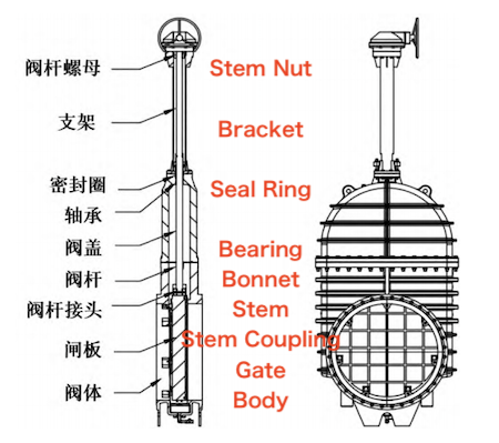
Figure 1: Rising Stem Flat-Bottom Gate Valve
Before machining, the materials for rising stem flat-bottom gate valves must be carefully chosen, as different materials necessitate different tools and machining processes.
Valve body, gate, and bonnet: Made of ductile iron (QT450-10), suitable for carbide, CBN, or PCD tools.
Stem and wedge-shaped top block: Made of stainless steel (06Cr19Ni10), suitable for CBN or PCD tools.
Trash tray: Made of stainless steel (06Cr19Ni10), fabricated using sheet metal techniques.
Gate nut and sleeve: Made of aluminum alloy (ZCuAl10Fe3), suitable for carbide tooling.
Remaining components: Standard parts readily available on the market.
Qualified raw materials are procured according to design specifications and inspected upon arrival to ensure compliance with quality standards. Using the company’s production management system—such as ERP or MES—production work orders are generated and executed following the system’s workflow. The rough machining datum is chosen according to relative position requirements. Typically, an unmachined surface is used as the rough datum to ensure accurate positional relationships between the unmachined and machined surfaces. For workpieces with multiple unmachined surfaces, the surface with the highest positional accuracy requirement is selected as the rough datum. Rough machining of the cast valve body removes burrs and excess material, preparing it for finish machining. Once it passes inspection, the workpiece advances to the next stage. The finishing datum is established based on the principle of datum coincidence. The design datum of the machined surface is directly used as the positioning reference to minimize alignment errors, reduce process tolerances, and facilitate high-precision machining. Finish machining is carried out on key areas of the valve body, including flanges and sealing surfaces, using high-precision machine tools and cutting tools to ensure accurate dimensions and superior surface quality. The machining process follows the principle of unified datums. During drilling and tapping, a consistent datum is employed to ensure accuracy, minimize cumulative errors, and enhance overall processing efficiency. Holes are drilled and tapped in the valve body and bonnet according to design specifications to facilitate the installation of bolts and other fasteners. To improve both corrosion resistance and appearance, flat-bottom gate valves are subjected to surface treatment processes, including grinding, sandblasting, and coating applications such as spraying. These treatments form a protective layer that enhances durability, prevents corrosion and wear, and improves the valve’s overall appearance. Before assembly, all components are thoroughly cleaned to remove oil and impurities. Soft sealing elements, such as sealing rings, are then installed on the gate to ensure dependable sealing performance. Assembly follows a precise sequence: the gate assembly is installed first, followed by the valve stem and bonnet, which are then integrated into the valve body. Finally, the electric actuator is installed and adjusted to ensure smooth operation, responsive opening and closing, and reliable sealing performance.
Sealing tests are conducted on the fully assembled valve. Testing may follow procedures for civil water supply valves or adhere to the national standard GB/T 13927-2022. The valve is tested at 1.1 times its nominal pressure. After holding this pressure for a specified duration, the valve is inspected for leaks to confirm that it passes the sealing test. Strength testing is performed to verify that the valve can withstand its designated operating pressure. In accordance with GB/T 13927-2022, the test is conducted at 1.5 times the nominal pressure. After holding the test pressure, the valve body, bonnet, and other pressure-bearing components are inspected to ensure no damage has occurred and that the valve meets the required strength specifications. Dynamic testing simulates real operating conditions, repeatedly cycling the valve between fully open and fully closed positions to verify smooth operation, effective sealing, and the absence of sticking or abnormal noise. Prior to testing, the valve is inspected to confirm it is free of damage, and the sealing surfaces are thoroughly cleaned of any debris. During testing, pressure is carefully controlled to prevent overpressure that could damage the valve. Upon completion, the valve is thoroughly inspected, and all test results are documented. It is important to note that specific testing procedures may vary depending on the valve type, its application, and relevant industry standards. Therefore, testing should adhere to the relevant standards and specifications. For valves intended for export, pressure tests must comply with BS ISO 5208, BS EN 12266-1, or other customer-approved standards.
Machining the valve seat hole of a parallel gate valve with conventional internal turning tools requires rotating the tool head, which makes the use of cutting fluid difficult. Additionally, the relatively low rigidity and hardness of the tool shank can lead to vibrations, making it difficult to maintain the required shape, positional tolerances, and surface quality of the valve seat hole. In the production of flat-bottom gate valves, the main challenges include machining the gate and ensuring the parallelism of the valve body sealing surface. Assembly challenges include ensuring the fit between the gate sealing surface and the wedge-type adjustment block, maintaining the flatness of the anti-debris tray and valve body flow channel, and addressing difficulties during assembly and debugging.
The gate groove has a serrated structure, as shown in the partial enlarged view in Figure 2. According to the design drawing, the large groove is machined first. After passing the sample inspection, the serrated groove is machined and verified using a serrated template. The template, made of stainless steel using wire cutting, must precisely match the design drawing and is used to measure and compare the machined grooves. Inspection verifies that the groove’s major diameter, minor diameter, depth, and slope fully conform to the template, ensuring compliance with design specifications. During subsequent processes, such as sandblasting and electrostatic spraying, the grooves must be carefully protected to prevent damage. Paint should be applied evenly within the grooves, avoiding drips or sagging. The paint film thickness is controlled at approximately 100 μm; excessive thickness can interfere with the rubber’s fit and reduce the smoothness of the seal ring. A self-sealing serrated seal is embedded within the groove and secured to the gate disc, ensuring that the single-sided sealing surface can withstand bidirectional pressure. Several wedge-shaped top blocks are arranged around the inner channel of the valve body, as shown in Figure 3, to ensure a tighter closure of the gate disc. Water entering the seal ring generates pressure at its base, forcing it outward to compensate for the gate disc’s deformation under load, thereby maintaining a consistent and tight sealing pressure.
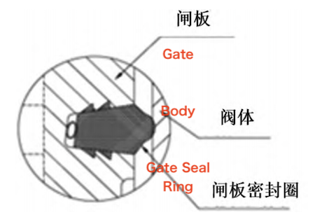
Figure 2: Enlarged view of the gate seal
Gate Vertical Lathe Machining:
Using the blank mesh surface as the reference base, the gate is first leveled and then machined. The slotted surface is subsequently leveled and grooved in accordance with the design specifications. Care must be taken to accurately control the slot’s center dimensions and depth, ensuring that all angles precisely match the design drawing. During slot serration, the angle of the serration cutter and its point of contact must be precisely calculated before machining. The next process can only proceed once lathing is complete and the workpiece has passed inspection.
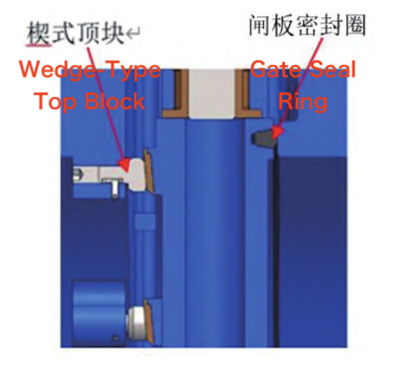
Figure 3: Structure of the Wedge-Type Ejector Block and Gate Seal
Boring Machine Machining:
Next, the gate is machined on a conventional boring machine to shape the guide rail surfaces. First, after rough milling and smoothing one side of the gate plate’s guide strip, the gate plate is positioned vertically on the workbench using this surface as a reference, ensuring a 90° angle with the workbench. The large slotted surface is then aligned parallel to the workbench. A pressure plate is used to secure the gate plate, while support welds are applied to the opposite surface to ensure it remains firmly perpendicular to the workbench. Next, the guide strips on both sides are milled, drilled, and tapped. Once the guide slots are properly positioned, the workbench is rotated to the specified angle, and the gate plate pads are milled to achieve the precise angles required by the design drawing. After milling, all machined surfaces are carefully inspected to ensure dimensional accuracy. Only once these inspections are successfully completed are the support and pressure plates removed, allowing the workpiece to proceed to the next stage of processing.
The initial turning steps are the same as previously described, with the primary difference arising when the milling process is carried out on the gantry machining center. The machined gate plate is first placed flat on the gantry machining center’s worktable, using the grooved surface as the reference. Next, the gate plate is centered, leveled, and clamped using a pressure plate. Guide grooves on both sides are then milled precisely according to the design specifications. After milling, the blank is lowered. A dedicated tool is then mounted on the gantry machining center’s worktable, and the blank is hoisted and accurately positioned onto the tool. The gate plate’s position is carefully adjusted, and a pressure plate is applied to secure it firmly. The top block of the gate plate is then milled to ensure that the machined surface precisely matches the design drawing. Finally, all machined dimensions are inspected to ensure they comply with design tolerances. Although this machining method provides high accuracy, it is relatively time-consuming and labor-intensive.
The machining accuracy and surface quality of the valve body’s sealing surface directly impact its sealing performance. Strict control of machining parameters and process flow is essential to achieve the required precision and surface finish. During turning, the flange and seat surface on one end of the valve body are machined first. Then, the flange, seat surface, and wedge-shaped top block surface on the opposite end are face-machined to ensure parallelism between the valve body sealing surface and the wedge-shaped top block mounting surface. It is essential that all machining be completed in a single clamping operation to preserve the parallelism of the valve seat surface.
During assembly, sealing performance depends on the alignment of the wedge-type top block, with a tighter seal achieved when the block is correctly positioned. A locking screw is used to adjust the position of the wedge-type top block in relation to the gate sealing surface. To make adjustments, first loosen the locking screw, then gradually tighten it to move the wedge-type top block forward until the gate disc sealing surface fully aligns with the valve body seat surface, as illustrated in Figure 4. Once alignment is achieved, tighten the locking screw and use a 0.1 mm feeler gauge to check for any gaps between the gate disc sealing surface and the valve body seat surface; no gap indicates proper alignment.
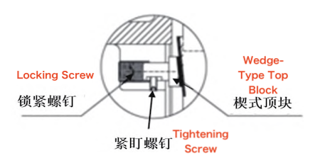
Figure 4: Enlarged view of a wedge-type top block with locking screw
The curved support plate is a purchased component. A template is fabricated according to the arc of the valve body flow path, and the material is deemed qualified when the template fits precisely against the arc surface of the curved support plate. Several springs are mounted beneath the curved support plate, as shown in Figure 5. These springs are housed within spring cylinders, which are fixed to the valve body grooves using epoxy adhesive. This design ensures that when the valve closes, the gate retracts downward to achieve a tight seal. When the valve opens, the springs automatically lift the curved support plate, leveling the groove and aligning it smoothly with the pipe bottom, as shown in Figure 6. The fixed spring cylinders prevent displacement during the curved support plate’s movement, ensuring a smooth and unobstructed flow path.
In flat-bottom gate valves, the guide grooves guide the gate during closure. The grooves feature stepped transitions at the junctions between the flow path, valve body, and bonnet, as illustrated in Figure 7. Since both the valve body and bonnet are cast, obtaining a smooth groove surface depends on precise casting and meticulous polishing. In conclusion, successful machining and assembly of flat-bottom gate valves require comprehensive consideration of material selection, structural design, machining order, and potential process difficulties. By adopting scientific machining techniques and implementing strict quality control measures, the performance and reliability of flat-bottom gate valves can be ensured to meet design specifications.
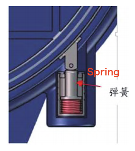
Figure 5. Spring structure
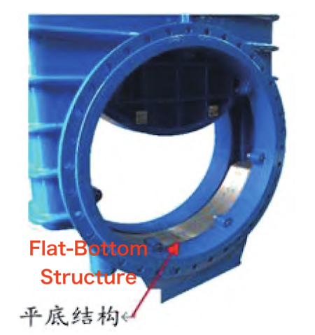
Figure 6. Flat-bottom structure
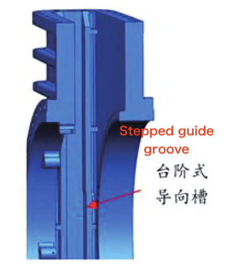
Figure 7. Stepped guide groove structure
The manufacturing of soft-seated flat-bottom gate valves is a highly intricate and precise process comprising several critical stages such as casting, machining, assembly, and performance testing. By analyzing the valve structure and materials, and addressing key production challenges—such as gate machining difficulty, parallelism of the valve body sealing surface, the fit between the gate sealing surface and the wedge-type top block, and the flatness of the anti-trash tray and valve body flow path—targeted solutions can be implemented to optimize manufacturing. The results indicate that improving processing techniques and machining accuracy can significantly enhance the quality, performance, and service life of electric rising-stem flat-bottom gate valves. Testing has confirmed stable product quality and a high first-pass yield, leading to reduced costs and improved production efficiency. The findings of this study provide a solid theoretical basis for addressing manufacturing challenges in large valves and offer strong support for optimizing the production process. Looking ahead, as manufacturing technologies continue to advance and processes are further optimized, the production of soft-seated flat-bottom gate valves will become increasingly precise, efficient, and reliable.