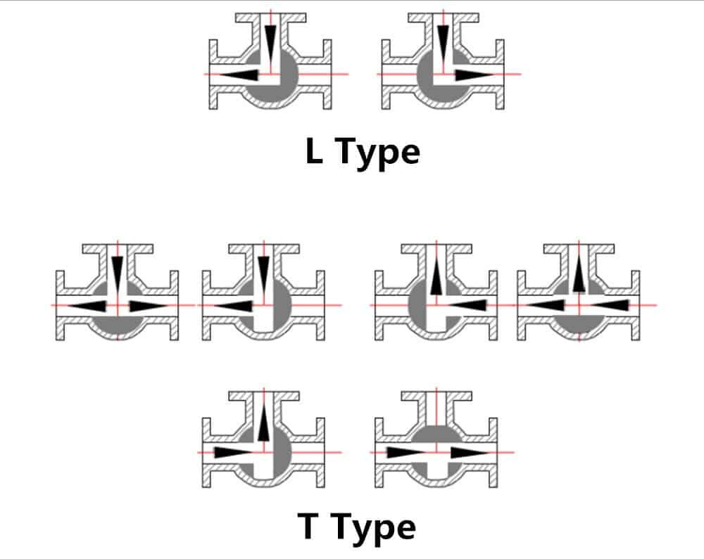
In pipelines, three-way ball valves are primarily used for cutting off, distributing, and changing the flow direction of the medium. They represent a relatively new category of ball valves with unique advantages such as frictionless operation, minimal seal wear, and low operating torque, allowing for smaller actuator specifications.

Three-way ball valves come in T-type and L-type configurations. T-type valves can interconnect three orthogonal pipelines and shut off the third channel, serving as a diverter or converger. L-type three-way ball valves can only connect two orthogonal pipelines at a time and cannot simultaneously maintain the interconnection of the third pipeline, serving only as a distributor.
1. Three-way ball valves adopt an integrated structure with a 4-seat sealing type, fewer flange connections, high reliability, and lightweight design.
2. They have a long service life, large flow capacity, and low resistance.
3. Three-way ball valves are classified into single-acting and double-acting types based on their operating modes. Single-acting valves will remain in the state required by the control system in case of a power source failure.
The three-way ball valve operates by rotating the valve stem to control the flow of fluid, allowing it to pass through or blocking it. These valves are characterized by their lightweight, compact design, ability to be manufactured in large diameters, reliable sealing, simple structure, easy maintenance, and resistance to erosion by the medium, making them widely utilized across various industries.
In pipelines, three-way ball valves serve primarily for the purposes of cutoff, distribution, and alteration of the flow direction of the medium. They belong to a relatively new category of ball valves offering unique advantages such as frictionless operation, minimal seal wear, and low operating torque, enabling the use of smaller actuator specifications.
There are two configurations of three-way ball valves: T-type and L-type. T-type valves can connect three orthogonal pipelines and close off the third channel, functioning as either a diverter or a converger. L-type three-way ball valves can only link two orthogonal pipelines at a time and cannot maintain the interconnection of the third pipeline simultaneously, serving solely as a distributor.
Three-way ball valves feature an integrated structure with a 4-seat sealing type, fewer flange connections, high reliability, and a lightweight design. They boast a long service life, high flow capacity, and low resistance.
Three-way ball valves are categorized into single-acting and double-acting types based on their operational modes. In the event of a power source failure, single-acting valves will maintain the state required by the control system.
Working Principle of Three-way ball valves
Opening Process:
1. In the closed position, the ball is mechanically pressed against the seat by the valve stem.
2. When rotating the handwheel counterclockwise, the valve stem moves in the opposite direction, causing the ball to disengage from the seat.
3. The valve stem continues to rise and interacts with the guide pin in the stem's spiral groove, allowing the ball to rotate without friction.
4. Until reaching the fully open position, where the valve stem reaches its limit position, and the ball rotates to the fully open position.
Closing Process:
1. During closure, rotate the handwheel clockwise, causing the valve stem to descend and initiate the rotation of the ball away from the seat.
2. Continue rotating the handwheel, and the valve stem, influenced by the guide pin embedded in its spiral groove, causes both the stem and the ball to rotate 90° simultaneously.
3. As closure approaches, the ball has rotated 90° away from the seat.
4. In the final few turns of the handwheel, the angular flat surface at the bottom of the valve stem mechanically wedges against the ball, tightly pressing it against the seat to achieve complete sealing.
Installation and Maintenance Precautions
1. Leave space for the valve handle to rotate.
2. Do not use for throttling.
3. Ball valves with drive mechanisms should be installed vertically.
