A valve is an essential pressure-bearing component of the boiler and is suspended on the boiler’s pipeline. If the valve body leaks or cracks during operation, it can pose significant risks to the safety of personnel and equipment. ZG20CrMoV, a low-alloy pearlite heat-resistant steel, is commonly used in boiler valves. It is characterized by good thermal strength. Carbide-forming elements like Cr, Mo, and V are primarily added to the steel. The addition of V leads to the formation of stable and dispersed VC particles with carbon in the steel, which benefits elements like Cr and Mo. These elements are integrated into the solid solution to strengthen the ferrite matrix, effectively improving the steel’s thermal strength. However, the steel exhibits poor fluidity during casting. Defects such as thermal cracks, impurity segregation, and surface gas holes easily form at the corners during casting, leading to stress concentration at variable sections. This paper examines the cracks in the main steam pipe globe valve of a newly installed boiler. Through on-site investigation, data collection, and laboratory analysis, this study explores the cause of the accident to provide a reference for improving valve manufacturing quality and preventing similar incidents.
A boiler under construction at a specific enterprise is designated QC330/920-110-10.1/540. It features an open-air layout, with a natural circulation steam-water system. The steam drum is fixed to the top platform steel frame, and the entire boiler furnace wall consists of a membrane water-cooled wall. The heating surface inside the furnace consists of a primary superheater, a secondary superheater, a bare tube evaporator, a finned tube evaporator, and a relatively independent finned tube economizer. The working pressure of the main steam pipe is 10.1MPa, and the working temperature is 540°C. The pipe specifications are 219 mm x 22 mm, made from 12Cr1MoVG. The valve model is J61Y-P54 170V-150, made from ZG20CrMoV.
In May 2020, the main steam pipe and branch pipe of the boiler were being installed and welded. There were six
globe valves on the platform, three of which (V1, V2, V3) developed cracks of varying degrees on the valve body side of their butt welds after welding. The quality certification documents for this batch of valves during the data review process was not found. Additionally, the valve manufacturer failed to provide these documents in a timely manner, so the relevant manufacturing information could not be obtained. The cracked globe valve is shown in Figure 1.
The surface of the butt welding seam on the cracked globe valve is well-formed, with a small amount of residual coating, and the welding seam has not been post-heat treated. Based on the paint peeling on the valve body, it can be inferred that preheating before welding used direct flame heating, which does not meet the relevant regulations. Specifically, when the outer diameter of the pipe exceeds 219 mm or the wall thickness exceeds 20 mm, flexible ceramic resistance heating, far-infrared radiation heating, or induction heating should be used.

Figure 1 Main steam platform and globe valves
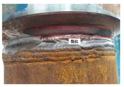
Figure 2 Cracks on valve V1
The part containing cracks on the lower side of the V1 valve was mechanically cut and sampled (see Figure 3). The chemical composition of the valve body sample was analyzed using a vacuum direct-reading spectrometer (GS1000-1, OBLF, Germany) (see Figure 4), and the chemical composition data obtained from the three measuring points are listed in Table 1. Table 1 shows that the phosphorus (P) and silicon (Si) content at the three measuring points exceeded the standard values, while the other chemical compositions were within a reasonable range.
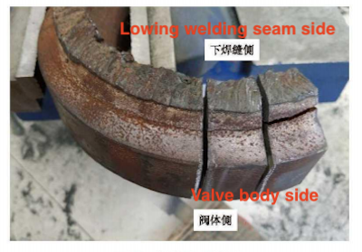
Figure 3 Sampling locations on the valve body
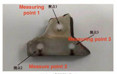
Figure 4 Test surface of the sample
Table 1 Chemical composition of the sample (%)
| Item |
Standard Value |
Measurement Point 1 |
Measurement Point 2 |
Measurement Point 3 |
| C |
0.18 - 0.25 |
0.25 |
0.26 |
0.26 |
| Mn |
0.40 - 0.70 |
0.69 |
0.68 |
0.66 |
| Si |
0.17 - 0.37 |
0.51 |
0.57 |
0.55 |
| Cr |
0.9 - 1.20 |
1.07 |
1.09 |
1.10 |
| Mo |
0.50 - 0.70 |
0.56 |
0.57 |
0.56 |
| V |
0.2-0.3 |
0.26 |
0.28 |
0.27 |
| S |
≤0.03 |
0.02 |
0.20 |
0.01 |
| P |
≤0.03 |
0.04 |
0.04 |
0.05 |
Note: The technical conditions for ZG20CrMoV are specified in JB/T 9625-1999, 'Technical Conditions for Pressure-Bearing Steel Castings for Boiler Pipe Accessories.
Mechanical polishing and chemical etching methods were used to perform metallographic analysis on the cracked V1 valve. Figure 5(a) shows the metallographic structure of the intact part of the valve, which includes needle-shaped martensite and ferrite. Figure 5(b) shows the metallographic structure at the crack tip, which includes martensite and ferrite, coarse grains, an uneven structure, and transgranular cracks.
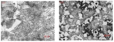
(a) Intact part (b) Crack tip
Figure 5 Metallographic structure of valve V1
Figure 6 shows the metallographic structure of a valve without cracks, which includes pearlite and block-shaped ferrite with coarse grains. It is evident that this structure differs from that shown in Figure 5(a).
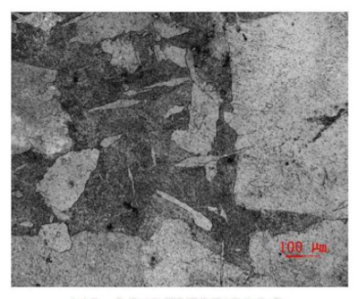
Figure 6 Metallographic structure of valve without cracks
A portable Leeb hardness tester (HT-2000A, G&B Technology) was used to test the hardness of both the cracked valve V1 and a crack-free valve. The hardness test sites were labeled A, B, and C, as shown in Figure 7. Each site was tested five times. The five test points were arranged in a horizontal line, with a distance of approximately 5 mm between adjacent points. Figure 8 shows the average hardness values for different sites of the two valves.
As shown in Figure 8, the average hardness values for the three parts of the crack-free valve fall within the range of 140–201 HB, meeting the requirements of the standard JB/T 9625-1999 "Technical Conditions for Pressure Castings of Boiler Pipe Accessories." In contrast, the average hardness values for the three parts of valve V1 exceed the upper limit. This suggests that the formation of a martensitic structure is the direct cause of the excessive hardness, which is consistent with the results of the metallographic analysis.
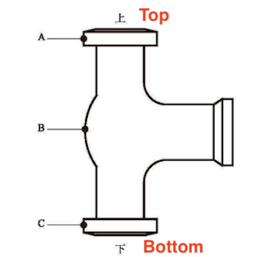
Figure 7 Hardness test site
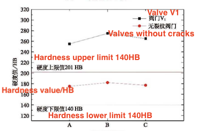
Figure 8 Hardness value of valve V1 and crack-free valve
Two 55 mm x 10 mm x 10 mm impact specimens were obtained from the intact part of the valve, as shown in Figure 9(a). The impact toughness values of the two specimens were 3.25 J/cm² and 3.10 J/cm², respectively, after the impact test at room temperature, which is far below the requirements of the standard JB/T 9625-1999 (impact toughness value ≥ 29 J/cm²). The macro fracture is crystalline, without an obvious shear lip, and is classified as brittle fracture, as shown in Figure 9(b).
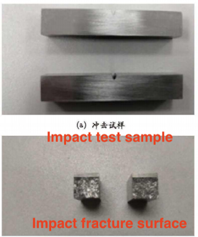
Figure 9 Impact test
The cross-section of the impact specimen was scanned using a scanning electron microscope (EVO18, Carl Zeiss, Germany). As shown in Figure 10, it displays characteristics of cleavage steps and fan-shaped river patterns, which are indicative of brittle cleavage surfaces. Brittle fracture can be divided into polycrystalline (cleavage) fracture and intercrystalline fracture pockets according to the microscopic crystal destruction mode. Cleavage fracture is a low-energy fracture that occurs along specific low-index crystallographic planes (rational planes) under the action of external normal stress. It is generally brittle, rarely undergoes plastic deformation, and has a crystalline cross-section with many strongly reflective planes. This plane is often the crystal plane with a higher atomic density in the crystal because its inter-plane atomic bonding ability is weaker, making it more prone to splitting when subjected to force. Brittle fracture often occurs in areas with holes, inclusions, and segregation generated during melting, reduction, grain purification, and casting.
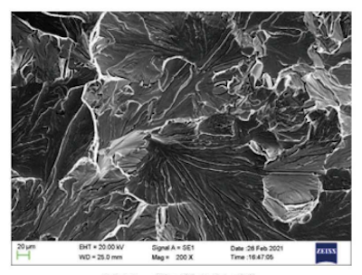
Figure 10 SEM morphology of the cross section


