Abstract: To control the connection or disconnection of solid particle wastewater in the system pipeline and prevent the backflow of seawater, effectively ensuring the long-term stable operation of the system. The forced opening and closing structure of the globe valve and the non return structure of the
lifting check valve are combined. This combination allows for the connection and disconnection of the medium in the system pipeline and prevents the backflow of the outlet medium. The combined design of the forced opening and closing structure of the globe valve and the non return structure of the lifting check valve effectively handles the discharge of medium with solid particles in the system pipeline, achieving the purpose of one valve for multiple uses.
The demand for multifunctional valves is increasing with the requirements for systematization, integration, and miniaturization. One valve can replace the original two, three, or even more valves, reducing the size of the system device and saving a significant amount of raw materials.
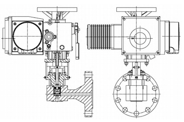
The technical parameters of the multifunctional valve designed in this paper are as follows: nominal size DN15, nominal pressure PN64, design temperature 164°C, safety level SC-2, seismic category 1A, and working medium including wastewater with solid particles, seawater, and internal electric drive. The multifunctional valve consists of a valve body, valve disc, spring, valve stem, valve bonnet, packing, packing gland, anti-rotation plate, fasteners, and an electric device, as shown in Figure 1.

Figure 1 Multifunctional valve structure drawing
The multifunctional valve can function as both a
globe valve and a check valve. The valve is designed with a detachable connection between the valve stem and the valve disc. The output torque of the electric device drives the valve stem up and down. When the valve stem is in the closed position, it holds the valve disc, functioning as a globe valve. The valve isolates the pipeline medium. When the valve stem is in the non return position, the valve disc moves freely, functioning as a check valve. The valve prevents the medium from flowing back. When the valve continues to open and the valve stem is in the fully open position, the valve disc is forced up, functioning as a globe valve. The valve connects the medium in the pipeline. Additionally, the electric device can remotely transmit these three position signals (open, non return, and closed) to the upper-level system.
3.1 Design of Valve Body
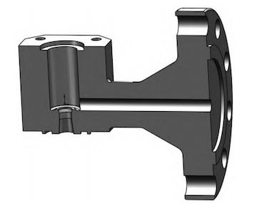
The valve body channel uses a full-size channel, and the sealing surface is designed to be flat to reduce pressure loss when the medium passes through. Because the valve disc is placed in the inner cavity of the valve body, affecting the flow performance of the medium, the design includes increasing the inner cavity size to avoid generating eddy currents and turbulence in the channel. The maximum opening height of the valve disc exceeds half of the channel size, and its curtain area is larger than the channel area. This combination design can reduce the flow resistance of the valve. The structure of the valve body is shown in Figure 2.

Figure 2 Valve body structure diagram
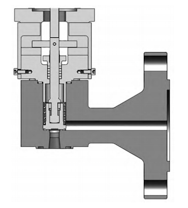
The valve body sealing surface and the valve disc sealing surface are made of metal, preventing internal leakage caused by potential corrosion. The width of the valve body sealing surface is smaller than that of the valve disc sealing surface, solving the problem of disc misalignment caused by cumulative tolerance in processing and assembly, and eliminating internal leakage due to misalignment of the valve body and valve disc. The design of the spring parts allows the valve disc to reset automatically, ensuring that the valve disc sealing surface fits the valve body sealing surface. At low check pressure, internal leakage sealing can be achieved. The valve disc can be installed at any angle, and the automatic reset function ensures proper operation. The valve stem parts are retained, enabling the forced closure of the valve disc, and the globe seal achieves zero leakage. The valve seat sealing system is shown in Figure 3.

Figure 3 Valve seat sealing system structure
3.3 Design of Sealing Structure Between Valve Body and Valve Bonnet
A reliable spiral wound gasket sealing structure is used between the valve body and the valve bonnet. By controlling the chlorine, sulfur, and fluorine content of flexible graphite, the rebound rate of the spiral wound gasket can be maintained for a long time in an irradiated environment. This sealing is reliable and effectively ensures the integrity of the pressure-bearing boundary.
The valve stem seal uses a mature flexible graphite packing sealing structure. By controlling the chlorine, sulfur, and fluorine content of flexible graphite, its rebound rate can be maintained for a long time in an irradiated environment. This sealing is reliable. The valve stem only moves up and down during use, prolonging the service life of the valve stem seal.
The valve body and valve disc sealing surfaces use a flat sealing structure. At the moment of closing, there is no mutual rotation; wear is minimal, and the reliability can reach more than 3,000 cycles.
Based on the stop and check functions, removing the limit plate allows the valve stem to drive the valve disc to continue moving. In this state, the valve disc is forced open, and the flow size matches the inner diameter of the pipeline, enabling rapid discharge of the medium.


