
Shock Resistance of Nuclear Grade Electric Gate Valves (Part Two)
5. Static analysis
5.1 Boundary condition setting
In the process of static analysis, the inlet and outlet of the gate valve are set as fixed constraints, and the load is applied to the gate valve system as shown in Figure 5.
(1) Considering the valve's weight, apply a standard gravitational acceleration g.
(2) Apply design pressure of 17.2 MPa and a design temperature of 350℃ to the inner wall of the gate valve.
(3) 4g SSE seismic load (D-type condition) and 10g design shock load are applied to the three directions of the gate valve system.
The thermal stress generated by the temperature difference between the inner and outer surfaces of the gate valve is applied to the gate valve system through the one-way coupling of heat and structure, and the convective heat transfer coefficient between the outer surface of the gate valve and the air is 5 W/(m2·K). The temperature cloud picture of the gate valve is shown in Figure 6.
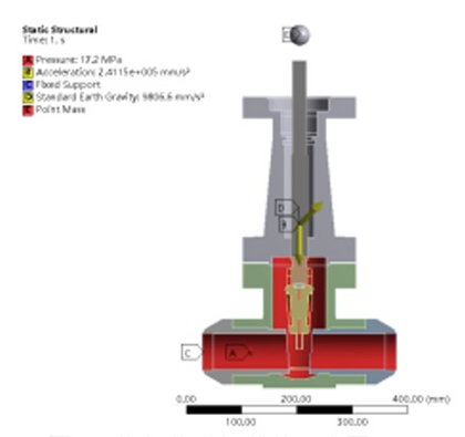
Figure 5 Constraints and loads
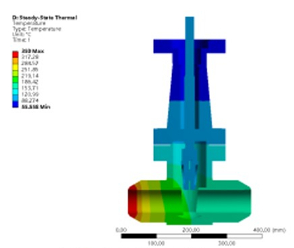
Figure 6 The cloud picture of the temperature of the gate valve
5.2 Analysis results and evaluation
According to the design conditions in Section 5.1, the overall total deformation and equivalent stress of the nuclear-level electric gate valve system are obtained through finite element analysis, as shown in Figure 7.
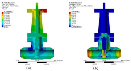
(a) Total deformation (b) Stress
Figure 7 The analysis results of total deformation and stress of the gate valve
It can be seen from Figure 7(a) that under the action of self-weights, internal pressure, thermal stress, seismic load and impact load, the overall deformation of the gate valve system is mainly concentrated in the upper half of the valve bonnet, and the maximum deformation amount is 0.72mm. The deformation of the valve body, valve seat and wedge is small, which will not affect the performance of the gate valve system. It can be seen from Figure 7(b) that under the above loads, the equivalent stress of the gate valve system is mainly concentrated in the valve body and valve seat, and the overall stress value is small. The thermal expansion effect cannot be released due to the fixed constraints applied on the inlet and outlet of the valve seat, resulting in great stress. Therefore, when evaluating the force bore by the valve seat, the stress distribution of the connection between the valve seat and the valve body is mainly evaluated. For the connection parts between the valve body and the valve seat and valve body, the maximum stress values are 276.5MPa and 250.9MPa, which are slightly higher than the yield strength of the valve body and valve seat materials, resulting in partial stress concentration. Increasing the fillet of the stress concentration part or adjusting the structure of the stress concentration part can reduce the degree of stress concentration.
In order to further evaluate the impact resistance of the nuclear-grade electric gate valve system, the stress evaluation lines (Figure 8) were selected at the dangerous sections of the valve body and the valve seat at the pressure-bearing boundary of the nuclear valve, and the linear stress evaluation was carried out according to the requirements of the ASME code. The calculation results of the stress evaluation line are shown in Figures 9 to 11. Because the load combination of the gate valve system adopts the category D limit accident condition, the stress evaluation criterion is that the membrane stress σm is less than 1.5S, and the sum of the membrane stress and bending stress is less than 1.8S, that is, σm plus σb are less than 1.8S, where S is material allowable stress. The evaluation results of the stress evaluation line at the dangerous section are shown in Table 3.
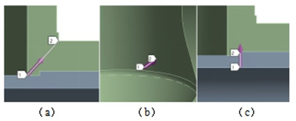
(a) Stress evaluation line 1 of valve bodies (b) Stress evaluation line 2 of valve bodies
(c) Stress evaluation lines of valve bodies
Figure 8 The selection of stress evaluation lines at dangerous sections of valve bodies and valve seats
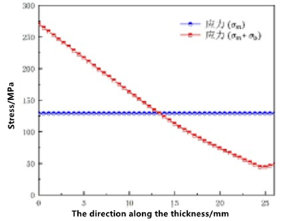
Figure 9 Stress distribution curve of stress evaluation line 1 of valve bodies
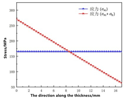
Figure 10 Stress distribution curve of stress evaluation line 2 of valve bodies
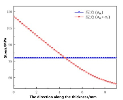
Figure 11 Stress distribution curve of stress evaluation lines of valve bodies
Table 3 Evaluation results of the stress evaluation line at the dangerous section
5.1 Boundary condition setting
In the process of static analysis, the inlet and outlet of the gate valve are set as fixed constraints, and the load is applied to the gate valve system as shown in Figure 5.
(1) Considering the valve's weight, apply a standard gravitational acceleration g.
(2) Apply design pressure of 17.2 MPa and a design temperature of 350℃ to the inner wall of the gate valve.
(3) 4g SSE seismic load (D-type condition) and 10g design shock load are applied to the three directions of the gate valve system.
The thermal stress generated by the temperature difference between the inner and outer surfaces of the gate valve is applied to the gate valve system through the one-way coupling of heat and structure, and the convective heat transfer coefficient between the outer surface of the gate valve and the air is 5 W/(m2·K). The temperature cloud picture of the gate valve is shown in Figure 6.
Figure 5 Constraints and loads
Figure 6 The cloud picture of the temperature of the gate valve
5.2 Analysis results and evaluation
According to the design conditions in Section 5.1, the overall total deformation and equivalent stress of the nuclear-level electric gate valve system are obtained through finite element analysis, as shown in Figure 7.
(a) Total deformation (b) Stress
Figure 7 The analysis results of total deformation and stress of the gate valve
It can be seen from Figure 7(a) that under the action of self-weights, internal pressure, thermal stress, seismic load and impact load, the overall deformation of the gate valve system is mainly concentrated in the upper half of the valve bonnet, and the maximum deformation amount is 0.72mm. The deformation of the valve body, valve seat and wedge is small, which will not affect the performance of the gate valve system. It can be seen from Figure 7(b) that under the above loads, the equivalent stress of the gate valve system is mainly concentrated in the valve body and valve seat, and the overall stress value is small. The thermal expansion effect cannot be released due to the fixed constraints applied on the inlet and outlet of the valve seat, resulting in great stress. Therefore, when evaluating the force bore by the valve seat, the stress distribution of the connection between the valve seat and the valve body is mainly evaluated. For the connection parts between the valve body and the valve seat and valve body, the maximum stress values are 276.5MPa and 250.9MPa, which are slightly higher than the yield strength of the valve body and valve seat materials, resulting in partial stress concentration. Increasing the fillet of the stress concentration part or adjusting the structure of the stress concentration part can reduce the degree of stress concentration.
In order to further evaluate the impact resistance of the nuclear-grade electric gate valve system, the stress evaluation lines (Figure 8) were selected at the dangerous sections of the valve body and the valve seat at the pressure-bearing boundary of the nuclear valve, and the linear stress evaluation was carried out according to the requirements of the ASME code. The calculation results of the stress evaluation line are shown in Figures 9 to 11. Because the load combination of the gate valve system adopts the category D limit accident condition, the stress evaluation criterion is that the membrane stress σm is less than 1.5S, and the sum of the membrane stress and bending stress is less than 1.8S, that is, σm plus σb are less than 1.8S, where S is material allowable stress. The evaluation results of the stress evaluation line at the dangerous section are shown in Table 3.
(a) Stress evaluation line 1 of valve bodies (b) Stress evaluation line 2 of valve bodies
(c) Stress evaluation lines of valve bodies
Figure 8 The selection of stress evaluation lines at dangerous sections of valve bodies and valve seats
Figure 9 Stress distribution curve of stress evaluation line 1 of valve bodies
Figure 10 Stress distribution curve of stress evaluation line 2 of valve bodies
Figure 11 Stress distribution curve of stress evaluation lines of valve bodies
Table 3 Evaluation results of the stress evaluation line at the dangerous section
| Stress evaluation lines of valve bodies | Calculated values | Allowable values | Calculated values | Allowable values |
| Stress evaluation line 1 of valve bodies | 128.9 | 229.5 | 270.7 | 275.4 |
| Stress evaluation line 2 of valve bodies | 165.1 | 229.5 | 270.3 | 275.4 |
| Stress evaluation lines of valve seats | 77.8 | 207 | 115.5 | 248.4 |
It can be seen from Table 3 that under the combined load impact, the maximum stress at the dangerous section of the valve body and valve seat is less than the allowable stress value, ensuring that the structural strength and pressure boundary of the nuclear-grade electric gate valve system are complete under the ultimate impact condition. The impact resistance performance requirements of nuclear-grade electric gate valve system can be met.
6. Conclusion
(1) The ANSYS Workbench software is used to calculate the mode shape and natural frequency of the nuclear-grade electric gate valve. The results show that the equivalent static method can be used to analyze the impact resistance of the nuclear-grade electric gate valve under combined load.
(2) Through the harmonic response analysis of the gate valve system, it is concluded that when the pressure-bearing boundary (valve bodies and valve seats) is subjected to the impact load that changes with time according to the simple harmonic law, the generated stress and deformation are small, and the structure is safe. The margin of safety is great.
(3) According to the equivalent static method simulation calculation, the nuclear-grade electric gate valve is subjected to the total deformation and equivalent stress under the action of internal pressure, thermal stress, self-weight, SSE seismic load and design impact load in the open state. The results show that under the impact of the above loads, the overall deformation of the gate valve system is mainly concentrated in the upper part of the valve bonnet; the maximum deformation is 0.72mm, and the deformation of other parts is small. After being impacted by the combined load, the stress distribution of the gate valve system is mainly concentrated in the valve body and valve seat, and the maximum stress value of both is slightly greater than the yield strength of the material, resulting in partial stress concentration. Increasing the fillet of the stress concentration part can reduce the degree of stress concentration.
(4) The impact resistance performance of the gate valve system is further evaluated by selecting the stress evaluation line on the dangerous section of the gate valve pressure-bearing boundary (valve bodies and valve seats). The results show that under the design conditions, the pressure boundary integrity of the nuclear-grade gate valve system is well maintained, and its shock resistance meets the design requirements.
