
Shock Resistance of Nuclear Grade Electric Gate Valves (Part One)
To study the shock resistance of nuclear-grade electric gate valves, a finite element model of the nuclear-grade electric gate valve under the combined action of design pressure, temperatures and design shock acceleration was established. Using ANSYS analysis software, the modal analysis of the valve was carried out, and the results showed that the impact resistance performance of the valve could be analyzed by the equivalent static method. The harmonic response and static characteristics of the valve under the combined load impact were analyzed based on the equivalent static method. The results of harmonic response analysis show that when the gate valve system is subjected to the impact load changed with time according to the simple harmonic law, the stress and deformation of the valve body and valve seat are far less than the allowable value, and the structural safety margin is great. The static analysis results show that the pressure boundary integrity of the valve is well maintained under the combined load, which meets the design requirements. The analysis of the impact resistance performance of nuclear grade electric gate valves under design conditions guides for the engineering design for this type of valve.
1. Overview
Nuclear grade gate valves are important devices widely used in systems of nuclear power plants, which are used to connect or cut off the medium in the pipeline. Because the nuclear grade gate valve is under high temperatures and high pressure, it is necessary to analyze the impact resistance of the gate valve system to avoid structural deformation or force exceeding the allowable value when it is subjected to impact load.
The traditional empirical formula calculation method cannot accurately reflect the internal force characteristics of the system structure. To solve this limitation, computer simulation technology has developed rapidly and is widely used in the analysis of the impact resistance of engineering structures. At present, the numerical analysis of the shock resistance of the valve mainly adopts the equivalent static method, the response spectrum method and the time domain simulation method. Equivalent static methods and response spectrum methods are simple and practical, and can accurately reflect the stress and strain of the system under impact load.
The time domain simulation method has high calculation accuracy, but the calculation process is relatively complicated, which is suitable for the analysis of the impact of complex structures. According to the equivalent static method, Xuelian Dong and others carried out a numerical simulation of nuclear grade wedge gate valves, and verified their seismic performance under seismic load. Yanpeng Lou and others simulated and tested the impact resistance of the angle globe valve based on the response spectrum analysis method. Yuanyang Jiao and others verified the impact resistance of marine globe valves under different loads through finite element analysis based on the time domain simulation method.
At present, there are few studies on the impact resistance of nuclear-grade electric gate valves in China. Therefore, a finite element model of nuclear grade electric gate valves is established in this article. Through modal analysis of the gate valve system, the equivalent static method is determined as the impact analysis method, and the internal pressure, thermal stress, seismic load and design impact load are comprehensively considered. The impact resistance of the gate valve system is evaluated by analyzing the harmonic response and static characteristics of the gate valve system.
2. Models and materials of valves
To improve the calculation efficiency and ensure the accuracy of the analysis results, the solid model of the gate valve is simplified; the connecting bolts between the gate valve components are ignored, and the structural features that do not affect the performance analysis results of the gate valve are deleted, such as chamfering and rounded corners. The electric device of the gate valve with complex structure is simplified as a mass point, and the simplified gate valve's solid model is shown in Figure 1. At the same time, a symmetrical boundary condition is set for the gate valve, and half of the model is taken for analysis. An unstructured mesh is used when dividing the mesh due to the great curvature of the gate valve's structure. Curvature is chosen for the size function. The maximum surface size is set to 4 mm. The number of mesh elements after division is 200765, and the element mass is 0.83. The mesh's quality is good. Its finite element calculation model is shown in Figure 2. The material of each component of the gate valve is shown in Table 1.
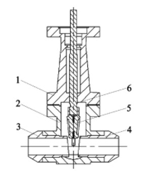
Figure 1 The structure of the gate valve
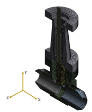
Figure 2 The finite element calculation model of the gate valve
Table 1 The material for each component of the gate valve
1. Overview
Nuclear grade gate valves are important devices widely used in systems of nuclear power plants, which are used to connect or cut off the medium in the pipeline. Because the nuclear grade gate valve is under high temperatures and high pressure, it is necessary to analyze the impact resistance of the gate valve system to avoid structural deformation or force exceeding the allowable value when it is subjected to impact load.
The traditional empirical formula calculation method cannot accurately reflect the internal force characteristics of the system structure. To solve this limitation, computer simulation technology has developed rapidly and is widely used in the analysis of the impact resistance of engineering structures. At present, the numerical analysis of the shock resistance of the valve mainly adopts the equivalent static method, the response spectrum method and the time domain simulation method. Equivalent static methods and response spectrum methods are simple and practical, and can accurately reflect the stress and strain of the system under impact load.
The time domain simulation method has high calculation accuracy, but the calculation process is relatively complicated, which is suitable for the analysis of the impact of complex structures. According to the equivalent static method, Xuelian Dong and others carried out a numerical simulation of nuclear grade wedge gate valves, and verified their seismic performance under seismic load. Yanpeng Lou and others simulated and tested the impact resistance of the angle globe valve based on the response spectrum analysis method. Yuanyang Jiao and others verified the impact resistance of marine globe valves under different loads through finite element analysis based on the time domain simulation method.
At present, there are few studies on the impact resistance of nuclear-grade electric gate valves in China. Therefore, a finite element model of nuclear grade electric gate valves is established in this article. Through modal analysis of the gate valve system, the equivalent static method is determined as the impact analysis method, and the internal pressure, thermal stress, seismic load and design impact load are comprehensively considered. The impact resistance of the gate valve system is evaluated by analyzing the harmonic response and static characteristics of the gate valve system.
2. Models and materials of valves
To improve the calculation efficiency and ensure the accuracy of the analysis results, the solid model of the gate valve is simplified; the connecting bolts between the gate valve components are ignored, and the structural features that do not affect the performance analysis results of the gate valve are deleted, such as chamfering and rounded corners. The electric device of the gate valve with complex structure is simplified as a mass point, and the simplified gate valve's solid model is shown in Figure 1. At the same time, a symmetrical boundary condition is set for the gate valve, and half of the model is taken for analysis. An unstructured mesh is used when dividing the mesh due to the great curvature of the gate valve's structure. Curvature is chosen for the size function. The maximum surface size is set to 4 mm. The number of mesh elements after division is 200765, and the element mass is 0.83. The mesh's quality is good. Its finite element calculation model is shown in Figure 2. The material of each component of the gate valve is shown in Table 1.
Figure 1 The structure of the gate valve
Figure 2 The finite element calculation model of the gate valve
Table 1 The material for each component of the gate valve
| Parameters | Wedges, valve bonnet and seats | Valve stems | Valve bodies |
| Grades | SA-182.F321 | SA-564.630 | SA-217.WC9 |
| Elastic Modulus/GPA | 195 | 196 | 202 |
| Yield strength MPa | 250 | 725 | 275 |
| Allowable stress MPa | 138 | 266 | 153 |
| Thermal conductivity/ (w.m-1℃-1) | 19.0 | 22.5 | 36.2 |
| Thermal expansion coefficient/ (×10-6℃-1) | 17.1 | 10.7 | 15.6 |
3. Model analysis
3.1 Boundary conditions
To truly reflect the modal characteristics of the gate valve in the open state, the inlet and outlet of the gate valve are set as fixed constraints. Because the thermal stress and positive pressure have little effect on the natural frequency of the valve, the modal analysis of the gate valve system is carried out by the method without prestress.
3.2 Calculation results and analysis
By analyzing the modal characteristics of the gate valve system in the open state, the mode shape and natural frequency of the gate valve system can be obtained. The calculation results are shown in Table 2.
Table 2 The first six natural frequencies of the gate valve
| Orders | 1 | 2 | 3 | 4 | 5 | 6 |
| Frequency | 85.81 | 223.18 | 252.76 | 557.09 | 733.92 | 1102.00 |
It can be seen from Table 2 that the first-order natural frequency of the gate valve system is 85.81Hz, which is greater than 33Hz. According to the requirements of ASME, the equivalent static method can be used to evaluate the impact resistance of the gate valve system by comprehensively considering the combined effect of the valve's weight, internal pressure, thermal stress, seismic load and impact acceleration.
4. Harmonic response analysis
4.1 Setting boundary conditions
To study the steady-state response characteristics of the gate valve system under the impact load that changes with time according to the simple harmonic law, the harmonic response analysis of the gate valve system is carried out. In the process of harmonic response analysis, the inlet and outlet of the gate valve are set as fixed constraints. The modal superposition method is adopted, and the influence of thermal stress on the gate valve system is ignored; the load is applied to the gate valve system at the same time.
(1) Apply design pressure of 17.2 MPa to the inner wall of the valve.
(2) The SSE seismic load of 4g (Category D condition) and the design shock acceleration of 10g (where g is a standard value of gravity acceleration) are applied to the three directions of the gate valve system.
4.2 Calculation results and analysis
Under the action of design pressure, seismic load and design impact load, the response curves of acceleration, stress and deformation changed with the frequency of the valve body and valve seat at the pressure-bearing boundary of the gate valve system were extracted, as shown in Figure 3 and Figure 4. It can be seen from Figure 3(a) and Figure 4(a) that the accelerations of the valve body and valve seat both increased with the increase of frequency, and reached the maximum value at 85Hz. It can be seen from Table 2 that 85Hz was the first-order natural frequency of the gate valve system, and its mode shape vibrated on the left and right of the X direction, that is, the acceleration in the X direction reached the maximum value, and the maximum values of the acceleration in the X direction of the valve body and the valve seat were 106630 mm/s2 and 3451.6 mm/s2. It can be seen from Figures 3 and 4 that the response curves of the stress and deformation of the valve body and valve seat were consistent with their acceleration change trends. When the valve body was at 85Hz, the stress response in the Y direction was the greatest, with a maximum value of 1.19MPa; the deformation response in the X direction was the greatest, with a maximum value of 0.37 mm. When the valve seat was at 85Hz, the X-direction stress and deformation response were the greatest, and the maximum stress and deformation responses were 0.59MPa and 0.012mm. The results show that when the gate valve system was subjected to the impact load that changed with the sinusoidal law, the stress and deformation of the pressure boundary valve body and valve seat were small, far smaller than the allowable value of the specification. The structural safety margin was great, and the integrity of the pressure boundary of the gate valve system was good.
Figure 3 The response curves of accelerations, stress and deformation of the valve body
Figure 4 The response curves of accelerations, stress and deformation of the valve seat
