Under actual operating conditions, a wedge-type double-disc gate valve used in boiler service experienced severe wear on the disc sealing surfaces, along with deformation of the guide slots in the valve body and the guide flanges on the discs. These failures resulted in significant damage to both the sealing surfaces and the overall valve structure, reducing the service life of the gate valve. In this study, the guide clearance dimensions were analyzed based on dimensional chain theory, the compressive stress of the guide slots was verified, and thermal-structural coupling simulations were conducted. The results show that excessive guide clearance prevented the two sealing discs from separating effectively during the lifting process, leading to wear. In addition, improper dimensions of the guide structure caused the compressive stress to exceed the allowable limit. Under long-term exposure to high-pressure and high-temperature conditions, the guide slots in the valve body underwent yielding and collapse. As a result, the discs tilted and exerted additional pressure on the sealing surfaces, causing further wear and damage. Based on these findings, the dimensions of the disc guide structure were optimized to satisfy stress requirements and reduce wear. This study provides a reference for the design and optimization of similar valves.
Valves are critical components in pipeline and gas-handling systems and serve as essential fluid control equipment in industries such as petroleum, chemical, power generation, aerospace, and marine engineering. A specific plant uses a wedge-type double-disc gate valve with a valve body bore diameter of 540 mm, a maximum disc travel of 623 mm, and a maximum working pressure of 5 MPa. Gate valves are widely applied due to their advantages, including low flow resistance, suitability for bidirectional flow, and long service life. During operation, an external mechanism drives the valve stem in the vertical direction. The stem is connected to the discs, and its movement directly controls the opening and closing of the valve. Fluid flow is regulated through the contact and separation between the disc sealing surfaces and the valve seats.
To prevent vertical displacement and lateral swinging of the discs, certain degrees of freedom must be restricted. This is achieved by integrating guide slots into the valve body and corresponding guide rails on the discs, allowing the two components to slide relative to each other. However, during actual operation, especially under the high-temperature and high-pressure conditions commonly encountered in steam boiler systems, severe structural damage occurred, as shown in Figure 1. Significant scuffing and surface collapse were observed on the discs, while yielding and flanging occurred in the guide slots of the valve body. These failures resulted in sealing failure and affected the normal operation of the valve.
In this study, the guide clearance of a boiler wedge gate valve was analyzed using the linear dimensional chain method. Theoretical calculations were conducted to determine the compressive stress acting on the guide rails under small-opening conditions. Furthermore, a thermal-structural coupling analysis was performed using ANSYS to obtain the displacement and stress distributions of the discs and guide rails. Based on the analysis results, the dimensions of the disc guide rails were optimized to mitigate wear and prevent structural failure during operation, thereby ensuring compliance with engineering requirements.
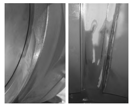
Figure 1. Photograph of structural failure of the gate valve under actual operating conditions
The gate valve consists of a valve body, bonnet, stem, spherical rings, spherical ring seats, gates, and valve seats. The assembly process begins with securing the valve body and installing the two valve seats into the inlet and outlet ends of the body cavity to ensure accurate dimensional alignment. The two gates are then assembled with the stem, spherical rings, and spherical ring seats. This gate assembly is subsequently inserted into the valve body cavity, where the wedge surfaces of the gates engage with the corresponding surfaces of the valve seats to establish sealing contact, while the spherical rings accommodate angular deviations during sealing. After the gate assembly is positioned, the guide rails on the gates engage with the guide grooves in the valve body and slide along them to ensure stable movement. Finally, the bonnet is assembled with the stem and valve body, completing the valve assembly. Figure 2 illustrates the assembly model in the fully closed position.

Fig. 2 Assembly drawing of the gate valve model
During the operation of the gate valve, the coupled movements among multiple components, together with strict requirements for manufacturing accuracy, introduce significant challenges to assembly and performance control. Among these factors, the sliding guide rail clearance is a critical design parameter that requires precise control. To ensure reliable valve operation, the guide rail clearance must be maintained within an appropriate range. Excessive clearance reduces guiding accuracy and may lead to issues such as vibration and impact, whereas insufficient clearance increases frictional resistance and operating torque, resulting in difficult operation and accelerated wear of the guide rails.
In essence, the guide rail clearance plays a critical role in ensuring smooth and stable gate movement and the reliable operation of the valve. Determining an appropriate clearance requires comprehensive consideration of multiple influencing factors. Considering the fit requirements, the assembly dimensional chain associated with the guide rail clearance must be analyzed and calculated. Since such valves are generally large in size and consist of numerous components, identifying the closing link of the dimensional chain and determining its nominal dimension and tolerance range provide an effective approach for optimizing the clearance to satisfy design requirements.
The primary components determining the guide rail dimensions include the valve body, valve seat, gate, spherical ring, and spherical ring seat. During valve operation, the spherical ring and its seat provide angular self-adjustment, enabling the gate sealing surface to align with the valve seat sealing surface and achieve reliable sealing performance. However, for the purpose of establishing and analyzing the assembly dimensional chain, these components can be neglected. Since the gate valve structure is symmetrical, only one half of the assembly is considered in the dimensional chain analysis, as shown in Fig. 3.
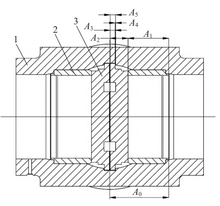
1. Valve body 2. Valve seat 3. Gate
Fig. 3 Schematic sectional view of the gate valve assembly
The dimension chain is established using the arrow method. Starting from either end of the closing link, a unidirectional arrow is drawn and extended along the entire dimensional chain, including the target dimension, until a closed loop is formed. The direction of each dimension is then determined relative to the closing link: dimensions with the same direction as the closing link are assigned positive values, whereas those in the opposite direction are assigned negative values.
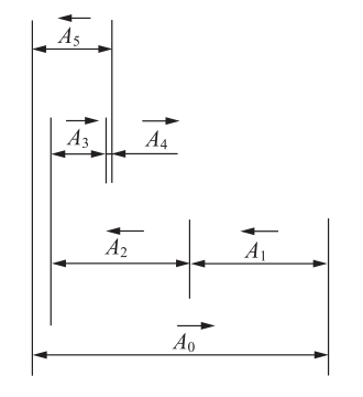
The dimensional chain of the closing link is illustrated in Fig. 4.
Fig. 4 Horizontal length dimension chain of the gate valve

Where:
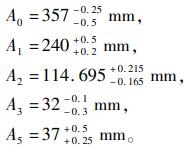
Because the nominal widths of the valve seat and gate are different, the centerline of the gate does not coincide with that of the valve seat when the valve is fully closed. Instead, a certain offset exists between the two centerlines. Therefore, dimension A2 is determined through geometric calculation based on the gate width.
Rearranging Equation (1) yields:

Substituting the numerical values into Equation (2), the nominal guide rail clearance is calculated as A4 = 2.695 mm.
T4=1.38 mm。

Where: 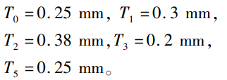
Substituting the numerical values into Equation (3), the guide rail clearance tolerance is calculated as:
T4 = 1.38 mm.
Based on the above calculations, the guide rail clearance of the gate valve after assembly is determined to be 5.4 mm. During gate lifting, the high-pressure fluid medium causes the gate to deviate from its centerline and shift toward the outlet-side valve seat. As the gate rises to a certain height, the guide rail grooves restrict its lateral movement, and the two sealing surfaces become fully disengaged only after further upward travel. Assuming that this required travel height is H (mm), the following algebraic and geometric calculation is performed:

During the initial 30.86 mm upward travel from the fully closed position, the two sealing surfaces remain in contact rather than separating, resulting in continuous wear of the sealing faces. Since both the valve body and gate are manufactured from F91 steel, which exhibits excellent oxidation resistance, high-temperature steam corrosion resistance, good impact toughness, and stable long-term mechanical properties at elevated temperatures, simulations at 540 °C show that although the overall dimensional chain of the model expands, the guide rail clearance remains essentially unchanged.
To further investigate the effects of this failure mechanism, considering the material properties and structural deformation caused by the operating temperature of 540 °C, a thermal-structural coupling simulation was performed using the ANSYS Workbench platform. The simulation model represented a boiler wedge gate valve under a 10% opening condition, consistent with actual operating conditions.
The interaction between temperature fields and stress fields is referred to as a thermal-structural coupling problem. Thermal-structural coupling is an analytical method that integrates temperature-field analysis with structural analysis and establishes their mutual interaction. By simultaneously considering thermal and structural characteristics, this method provides simulation results that more accurately represent actual operating conditions. Thermal-structural coupling analysis requires not only the governing equations for heat transfer and solid mechanics to be satisfied but also the coupling relationships between thermal and structural fields.
The gate valve investigated in this study has a body bore diameter of ϕ540 mm and a maximum gate travel of s = 623 mm. Due to the large number of components in the valve assembly, direct finite element analysis would result in excessive computational cost. Therefore, appropriate simplification of the original model is required. The simplification process aims to remove components that have negligible influence on the analysis results, thereby improving mesh quality and computational efficiency, while ensuring that the simplified model accurately represents the actual operating conditions of the valve.
Based on these principles, only the valve body, gate, valve seat, bonnet, and stem were retained in the simplified model, whereas components such as the stem packing, gaskets, gland, and handwheel were omitted. The three-dimensional model established in SolidWorks is shown in Fig. 5.
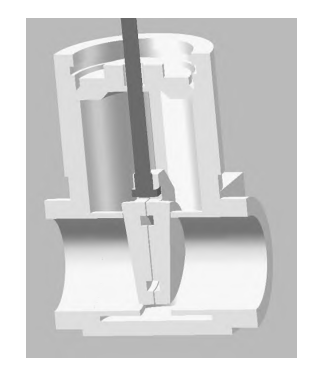
Fig. 5 Simplified 3D model
Table 1 Material properties
Part | Material Grade | Density (kg/m³) | Elastic Modulus (×10³ MPa) | Poisson’s Ratio | Linear Expansion Coefficient (×10⁻⁶ mm/(mm·°C)) |
Valve body, gate, valve seat, bonnet | 10Cr19Mo1VNbN | 7750 | 174 | 0.30 | 13.01 |
Stem | 38CrMoAlA | 7850 | 174 | 0.27 | 11.94 |
The boiler gate valve operates under severe conditions, with an operating temperature of 540 °C and an operating pressure of 5 MPa, requiring the use of high-temperature-resistant materials. The valve body, gate, valve seat, and bonnet are manufactured from 10Cr9Mo1VNbN, while the valve stem is made of 38CrMoAlA. The material properties are provided in Table 1, and the finite element mesh of the solid model is shown in Fig. 6.
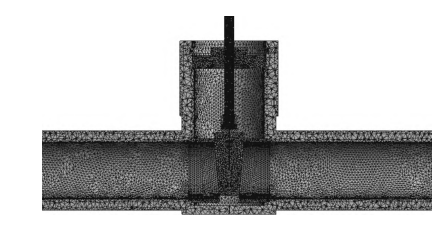
Fig. 6 Finite element mesh of the solid model
According to the actual installation conditions of the valve, a fixed support is applied at the pipeline inlet, while displacement constraints are imposed at the outlet. A pressure load of 5 MPa is applied to the inlet surface, and the outlet is assumed to be under free discharge conditions. For the thermal boundary conditions, the fluid-wall interface is defined as a stationary wall, with the reference pressure set to atmospheric pressure. To simulate the thermal and mechanical effects caused by high-pressure flow during small-opening operation, the fluid region is coupled with a temperature field of 540 °C, while the outer surface of the valve body is assumed to be thermally insulated.
The boundary conditions applied to the solid region are shown in Fig. 7. Specifically, Position A is defined as a fixed support; Position B permits displacement in the X-direction while constraining displacement in the Y- and Z-directions; and Position C is subjected to an internal pressure of 5 MPa.
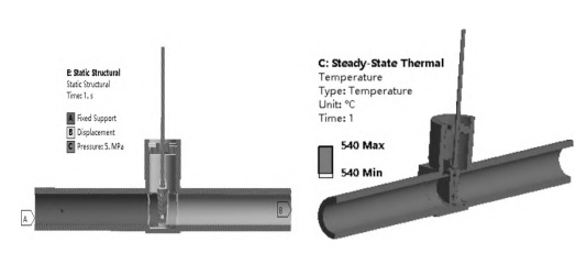
Fig. 7 Schematic of boundary conditions and loads applied to the solid model
Due to dimensional limitations of the guide rail slots in the valve body, when the gate is lifted beyond 30.86 mm, further upward movement causes contact between the gate guide rail and the valve body guide rail slot. Under the action of high-pressure fluid, bearing stress is generated at the contact surfaces. Therefore, calculating this stress is necessary to verify whether it satisfies engineering requirements.
According to the ASME Boiler and Pressure Vessel Code, Section II, Part D: Properties (2015 Chinese Edition) [1], the maximum allowable stress of F91 steel at temperatures below 550 °C is 103 MPa. The allowable bearing stress is taken as 1.5 times the maximum allowable stress.
In the theoretical calculation, the contact pressure on the bearing surface is assumed to be uniformly distributed.
Bearing stress formula:
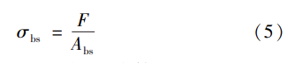
Where: Abs is the crushing area, calculated from the geometric dimensions as 7517.52 mm²; F is the force transmitted through the crushing surface, which here is the static pressure of the medium on the sealing surface, given by:

Where: DMW — Outer diameter of the valve seat sealing surface
P — Design pressure
Corresponding theoretical calculation of bearing stress:
Theoretical calculations indicate that the bearing stress at the guide rail contact surface exceeds the allowable bearing stress of 154.5 MPa. During long-term operation, the guide rail groove is prone to yielding and collapse, forming a "lip" or flange. This creates the potential for gate displacement and tilting, leading to continuous crushing against the sealing surface and resulting in severe wear.

Figure 8 presents the displacement contour of the gate structure under coupled high-temperature and high-pressure conditions. The maximum displacement of 33.88 mm occurs at the inlet-side bottom of the gate, while the upper part of the gate shifts approximately 4 mm toward the fluid inlet. Due to insufficient constraint from the guide rail groove, the entire gate undergoes tilting deformation, which is consistent with the actual operating behavior. The stress distribution on the gate guide rail is shown in Fig. 9. The maximum stress at the contact surface between the gate guide rail and the valve body guide rail groove reaches 171 MPa, exceeding the allowable bearing stress of 154.5 MPa.

Thermal expansion increases the contact area between the guide rail and the guide rail groove. As shown in Equation (8), the relative error between the simulation result and the theoretical calculation is small, confirming the reliability of the thermal-structural coupling simulation method.
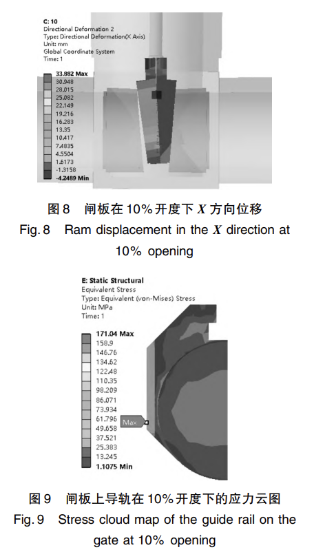
Fig. 8 Displacement of the gate in the X-direction at 10% opening
Fig. 9 Stress contour map of the guide rail at 10% opening
Due to the limited contact area between the guide rail and the guide slot, the guide slot in the valve body is subjected to excessive bearing stress under the combined effects of high fluid pressure and thermal expansion at elevated temperatures. During long-term operation, the guide slot undergoes plastic deformation and eventually collapses, resulting in lip formation. Consequently, the gate loses effective lateral constraint, causing tilting and repeated abnormal contact between the sealing surfaces. This mechanism is the primary cause of sealing surface wear and subsequent sealing failure.
Analysis of the guide rail clearance based on the dimensional chain principle indicates that excessive clearance requires the gate to travel a considerable distance upward before the sealing surfaces fully separate and wear is eliminated. Theoretical calculations and simulation results show that, for this type of boiler wedge gate valve, under small-opening conditions, the combined effects of high temperature and a large pressure differential cause the gate guide rail to become tightly engaged with the valve body guide slot. The resulting small contact area generates excessive bearing stress, leading to deformation and collapse of the guide slot, including lip formation, which subsequently causes abnormal contact and wear of the sealing surfaces.
Considering manufacturing feasibility and cost, an effective approach to address this problem without modifying the fundamental structural parameters or operating characteristics of the gate is to optimize the geometric dimensions of the gate guide rail. By adjusting the guide rail dimensions, the clearance can be optimized to improve the contact condition, reduce excessive bearing stress, and minimize deformation caused by thermal and pressure-induced loads.
The structural optimization of the gate guide rail is illustrated in Fig. 10. In the optimized design, dimension L is increased by 1.5 mm, dimension H by 3 mm, and dimension D by 1.7 mm. After optimization, the guide rail clearance is recalculated using the same dimensional chain approach:

Where: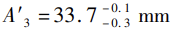
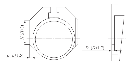
Fig. 10 Schematic of the optimized guide rail structure on the gate
Calculations of the required wear travel indicate that a stem lift of 11.3 mm is sufficient to separate the two sealing surfaces, thereby reducing wear and improving sealing reliability.
A theoretical calculation of the bearing stress was performed for the contact area between the gate guide rail and the valve body guide groove:

Where: A′bs represents the improved contact area, which geometric calculations give as 8690.22 mm². Theoretical calculations following the modification of the gate guide rail dimensions confirmed that the compressive stress between the guide rail and the guide groove met the requirements.
Thermal-structural coupling simulations were performed under the same operating conditions, and the displacement contour of the optimized gate structure is shown in Fig. 11. The maximum displacement of the gate was reduced to 4.6 mm, satisfying the engineering requirements. The stress contour of the gate guide rail is shown in Fig. 12. After optimization, the bearing stress at the contact interface between the gate guide rail and the valve body guide groove decreased to 149.2 MPa.

Equation (11) shows that the relative error between the simulation result and the theoretical calculation is small. In addition, the bearing stress at the contact interface was reduced below the allowable value, indicating that the optimized design satisfies the strength requirements.
Therefore, reducing the guide rail clearance and increasing the contact area between the gate guide rail and the valve body guide groove effectively address the aforementioned practical issues.

Fig. 11 X-direction displacement contour of the optimized gate at 10% opening
Fig. 12 Stress contour of the optimized gate guide rail at 10% opening
Based on the dimensional chain analysis, theoretical calculations, and thermal-structural coupling simulations of the boiler wedge-type double-disc gate valve, the following conclusions can be drawn:
(1) Dimensional chain analysis shows that excessive guide rail clearance prevents the two sealing surfaces from separating promptly during valve opening, resulting in increased wear travel and accelerated wear of the sealing surfaces.
(2) The theoretical bearing stress calculations show good agreement with the simulation results, verifying the accuracy of the calculation method and the reliability of the simulation analysis.
(3) Under small-opening conditions, the combined effects of high temperature and high fluid pressure reduce the effective contact area between the gate guide rail and the valve body guide groove, causing the bearing stress to exceed the allowable limit. During long-term operation, excessive bearing stress leads to plastic deformation and collapse of the guide groove, resulting in lip formation. Consequently, the gate loses effective lateral constraint, undergoes tilting deformation, and produces abnormal contact with the sealing surfaces, leading to further wear and sealing failure.
(4) After optimizing the geometric dimensions of the gate guide rail, the wear travel distance is significantly reduced according to the same calculation method. The bearing stress at the contact interface between the guide rail and guide groove is reduced below the allowable limit, and the maximum displacement is limited to 4.6 mm, satisfying engineering requirements. The results provide a theoretical basis for the structural optimization and reliability improvement of this type of valve.