Abstract: To mitigate flow-induced noise in pipe bends downstream of butterfly valves, a common configuration in large-diameter marine piping systems, and minimize its interference with acoustic devices, a porous-media-based noise control strategy is proposed. Its noise-reduction performance is evaluated through numerical simulations and experimental validation. The study involves:
Numerical simulation: Detached Eddy Simulation (DES) is used to investigate flow noise at three different flow velocities.
Experimental validation: Tests are conducted on a DN200 high-pressure, gas-driven water-flow test rig at Huazhong University of Science and Technology.
The results demonstrate that the proposed porous-media-based strategy effectively reduces flow noise in pipe bends downstream of butterfly valves in large-diameter piping systems. The greatest noise reduction is achieved at a Reynolds number of (7.8×10⁵), with an 8.52 dB reduction in the overall sound pressure level (OASPL) over the 10–1,000 Hz frequency range. These findings confirm the effectiveness of porous media as a means of controlling flow-induced noise in downstream pipe bends.
Porous-media flow control is a biomimetic technique inspired by the unique feather structures that enable owls to fly almost silently. In recent years, this approach has attracted considerable attention for its potential to suppress flow-induced noise. Porous media have been widely recognized for their ability to reduce flow-induced noise, as demonstrated by numerous experimental studies. Sueki et al. were the first to investigate the use of porous media for bluff-body noise reduction. Their wind tunnel experiments showed that open-cell metal foam could reduce aerodynamic noise by up to 18 dB. Naito et al. subsequently demonstrated that porous media can stabilize the wake behind a cylinder and significantly suppress vortex shedding at high Reynolds numbers. Further studies by Geyer et al., Aguiar et al., and Liu et al. involved acoustic measurements of cylinders covered with porous materials. Their findings consistently confirmed the effectiveness of porous media in suppressing bluff-body vortex-shedding noise.
In general, porous media can reduce flow-induced noise through several mechanisms:
- Suppressing vortex formation and development.
- Reducing the vortex-shedding frequency.
- Dissipating small-scale vortices.
Research into flow-induced noise sources in pipes has shown that dipole sources generated by the interaction between pressure fluctuations and pipe walls are dominant. Porous media are particularly suitable for weakening these sources by attenuating pressure fluctuations and modifying the near-wall flow field. Therefore, the application of porous media offers considerable potential for reducing flow-induced noise in piping systems.
A butterfly valve regulates flow by rotating a disc-shaped closure element. Owing to its simple construction, ease of operation, favorable flow control characteristics, and reliable sealing performance, it is widely used in large-diameter marine piping systems, particularly in seawater intake and discharge lines. However, flow through butterfly valves can generate considerable noise under actual operating conditions. The resulting noise is often concentrated along the walls of the downstream pipe bend, potentially compromising vessel stealth, interfering with underwater acoustic detection, and disrupting fishing activities. In addition, this noise pollution can adversely affect the marine environment and aquatic life.
To address these issues, this study proposes a porous-media-based approach to controlling flow-induced noise and turbulence in piping systems, with a particular focus on the pipe bend downstream of a butterfly valve. Porous media are applied to the inner wall of the bend to dissipate turbulent kinetic energy generated by the upstream valve and attenuate pressure fluctuations along the pipe wall, thereby reducing flow-induced noise.
A large-diameter pipe bend located downstream of two butterfly valves installed at 180° to each other was selected as the study object. Both upstream butterfly valves were fully open. To implement the porous-media-based flow noise control scheme (hereafter referred to as the control scheme), a porous medium layer of a specified thickness was applied to the outer wall of the bend's inner surface. The geometric configuration of the control scheme is shown in Fig. 1. The porous medium helps suppress interactions between the wake vortices and corner vortices generated by the upstream butterfly valves and the outer wall of the pipe bend. This reduces pressure fluctuations and sound source intensity in the bend, thereby mitigating flow-induced noise in the pipe.
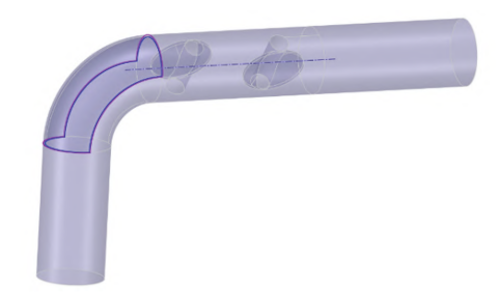
Fig. 1 Geometric configuration of the porous-media-based flow noise control scheme
The computational domain was assigned a velocity-inlet boundary condition at the inlet and a pressure-outlet boundary condition at the outlet, while all remaining surfaces were treated as no-slip walls. Both butterfly valves were fully open. Second-order upwind schemes were employed for spatial discretization, and a second-order implicit scheme was used for temporal discretization. Numerical simulations were performed for both the original geometry and the control scheme at a Reynolds number of Re = 7.8×10⁵.
The computational mesh was generated using the ANSYS automatic meshing tool. The mesh quality parameters are summarized in Table 1. Mesh independence was assessed by comparing the line spectra obtained using meshes with different refinement levels. The coarse mesh failed to adequately capture the line-spectrum characteristics within the frequency range of interest, whereas the medium and fine meshes produced nearly identical results. Considering the computational cost, the medium mesh was selected for subsequent simulations.
Table 1 Mesh Quality Parameters
Mesh Level | First-Layer Boundary Layer Height (10⁻⁶ m) | Number of Cells (10⁴) | Average Orthogonal Quality |
Coarse | 26 | 298 | 0.954 |
Medium | 13 | 456 | 0.953 |
Fine | 9 | 597 | 0.956 |
The vorticity and velocity contours of the original pipe-bend configuration and the proposed control scheme are shown in Figs. 2 and 3, respectively. As illustrated, the porous medium layer serves two main functions:
Vortex isolation and energy dissipation: It separates the large-scale, high-energy vortical structures generated by the upstream butterfly valves from the outer-radius wall of the pipe bend. This helps dissipate the turbulent kinetic energy of the incoming flow structures and weakens wall-mounted dipole acoustic sources, thereby reducing flow-induced noise in the bend.
Flow guidance: The porous medium layer also provides a degree of flow guidance, helping to improve the flow characteristics within the bend.
Preliminary numerical results indicate that the porous medium effectively suppresses pressure fluctuations within the pipeline, particularly along the inner wall of the pipe bend, thereby reducing the radiated sound pressure.
The sound field was calculated using the Ffowcs Williams–Hawkings (FWH) equation, and the sound pressure in the pipe was measured. Once the flow field reached a statistically steady state, 5 s of data were collected for discrete Fourier transform (DFT) analysis to obtain the sound pressure spectrum at a Reynolds number of (7.8×10⁵), as shown in Fig. 4. The results show that the porous-media-based control scheme achieves significant noise reduction, particularly in the low-frequency range, while its effectiveness in reducing high-frequency noise is relatively limited. This finding is consistent with the vorticity and velocity contours, which indicate that the porous medium layer dissipates the energy of large-scale, high-energy turbulent structures. A comparison of the overall sound pressure levels (SPLs) at the measurement point over the 10–1,000 Hz frequency range shows that the original configuration has an SPL of 86.10 dB, whereas the control scheme reduces it to 72.94 dB, corresponding to a reduction of 13.16 dB.
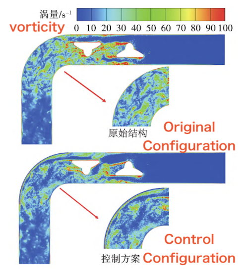
Fig. 2 Vorticity contours of the original structure and the control scheme
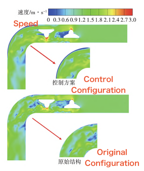
Fig. 3 Velocity contour of the original structure and the control scheme
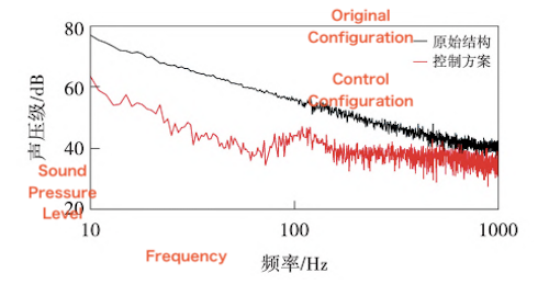
Fig. 4 Sound pressure spectrum of the control scheme
Additional simulations were conducted at Reynolds numbers of Re = 3.9×10⁵ and 5.1×10⁵. The overall sound pressure levels (SPLs) over the 10–1,000 Hz frequency range under all three operating conditions are summarized in Table 2. The noise reduction achieved by the control scheme was calculated as the difference between the SPL of the original configuration and that of the control scheme at the same Reynolds number. The results show that the noise reduction is relatively limited at lower Reynolds numbers but becomes more pronounced as the Reynolds number increases.
Table 2 Noise Reduction Performance of the Control Scheme
Configuration | Reynolds Number ((Re/10^4)) | Overall SPL (dB) | Noise Reduction (dB) |
Original structure | 3.9 | 66.33 | 0 |
Original structure | 5.1 | 68.76 | 0 |
Original structure | 7.8 | 86.10 | 0 |
Control scheme | 3.9 | 60.35 | 5.98 |
Control scheme | 5.1 | 63.60 | 5.16 |
Control scheme | 7.8 | 72.94 | 13.16 |
The effects of the porous medium resistance coefficients on noise reduction and flow resistance were evaluated by varying the viscous and inertial resistance coefficients while keeping the porosity constant at 1. All simulations were performed under identical operating conditions, and the results are presented in Table 3.
Table 3 Effects of Porous Medium Resistance Coefficients on Noise Reduction and Flow Resistance
Viscous Resistance Coefficient | Inertial Resistance Coefficient | Noise Reduction (dB) | Change in Flow Resistance (%) |
500,000 | 500 | 13.16 | 3.67 |
50,000 | 50,000 | 10.64 | −5.84 |
500 | 50,000 | 7.14 | −1.23 |
500 | 500 | 3.64 | −2.41 |
Here, the drag increase ratio is defined as the increase in drag relative to the original structure, expressed as a percentage of the drag of the original structure. The results show that appropriate combinations of the viscous and inertial resistance coefficients can enhance drag in the controlled section of the pipe wall while effectively reducing flow-induced noise. For the parameter combination that delivers the greatest noise reduction, the drag increase ratio remains below 5%, indicating that the proposed control scheme can achieve substantial noise reduction with only a modest increase in flow resistance, making it suitable for practical applications.
A high-pressure, gas-driven water-flow test rig was constructed to experimentally validate the proposed porous-medium control scheme. A schematic of the test rig is shown in Fig. 5.
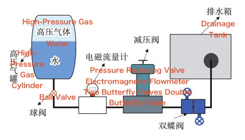
Fig. 5 Schematic of the Experimental Setup
The porous medium was installed along the outer-radius wall of the pipe bend downstream of the two butterfly valves. It was intended to weaken the interaction between the wake vortices and corner vortices generated by the upstream butterfly valves and the bend wall, thereby reducing pressure fluctuations and the strength of wall-associated dipole sound sources and suppressing flow-induced noise in the bend.
Because porous-medium sheets are difficult to reshape after fabrication, they cannot readily be adapted to the specific geometry of a pipe wall or modified to achieve different internal structural parameters. To address these limitations, nTop software was used to develop a three-dimensional (3D) CAD model of the porous microstructure. The model was tailored to the geometry of the pipe bend and subsequently fabricated using metal additive manufacturing.
A high-pressure, gas-driven water-flow test rig was used to evaluate the noise reduction performance of the proposed control scheme. Two sound pressure measurement points were established: one on the pipe bend and the other on its downstream outer side, as shown in Fig. 6. Multiple tests were conducted on the pipe bend downstream of the two butterfly valves. The results demonstrate that the proposed control scheme achieves effective noise reduction at both Reynolds numbers (Re = 5.1 × 10⁵ and Re = 7.8 × 10⁵). Furthermore, the measured sound pressure level characteristics are consistent with the numerical simulation results.
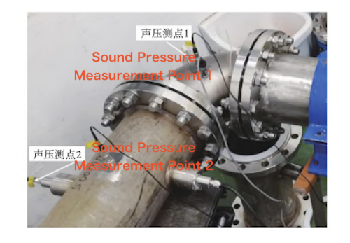
Fig. 6 Schematic diagram of the sound pressure measurement points
The time-domain measurement data obtained at Re = 5.1 × 10⁵ were transformed into the frequency domain. The frequency axis was plotted on a logarithmic scale, and the resulting spectra are shown in Fig. 7. As shown in Fig. 7, the proposed control scheme achieves effective noise reduction near 300 Hz at measurement point 1, while a more pronounced noise reduction effect is observed near 100 Hz at measurement point 2.
At Re = 5.1 × 10⁵, the overall sound pressure levels measured at the two measurement points over the 10–1000 Hz frequency band are presented in Table 4. Compared with the original structure, the proposed control scheme reduces the overall sound pressure level by up to 4.2 dB across this frequency band.
Table 4 Overall sound pressure levels at the two measurement points over the 10–1000 Hz frequency band at Re = 5.1 × 10⁵
Configuration | Measurement point 1 / dB | Measurement point 2 / dB | Noise reduction / dB |
Original structure | 157.77 | 156.88 | 0 |
Proposed control scheme | 153.25 | 153.04 | 4.20 |
The frequency-domain results obtained at Re = 7.8 × 10⁵ are presented in Fig. 8. As shown in Fig. 8, the proposed control scheme achieves substantial noise reduction at measurement point 1, located at the elbow, over a broad frequency range of 10–200 Hz. In particular, the noise peaks observed in the original structure within the 50–100 Hz range are almost completely eliminated, demonstrating effective suppression of flow-induced noise in this frequency band. This finding is consistent with the numerical results presented in Section 2. At measurement point 2, the proposed control scheme is particularly effective in reducing noise in the low-frequency range of 20–30 Hz.
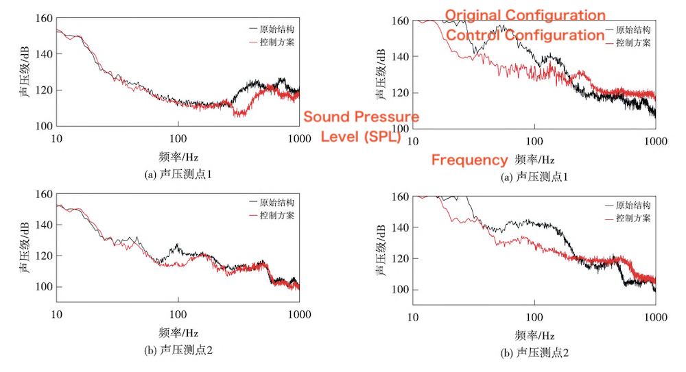
(a) Sound pressure measurement point 1(b) Sound pressure measurement point 2
Fig. 7 Sound pressure level spectra at Re = 5.1 × 10⁵
(a) Sound pressure measurement point 1 (b) Sound pressure measurement point 2
Fig. 8 Sound pressure level spectrum at Re = 7.8×10⁵
At Re = 7.8 × 10⁵, the overall sound pressure levels measured at the two measurement points over the 10–1000 Hz frequency band are presented in Table 5. Compared with the original structure, the proposed control scheme reduces the overall sound pressure level by up to 9.69 dB across this frequency band.
Table 5 Overall sound pressure levels at the two measurement points over the 10–1000 Hz frequency band at Re = 7.8 × 10⁵
Configuration | Measurement point 1 (dB) | Measurement point 2 (dB) | Noise reduction (dB) |
Original structure | 171.73 | 169.72 | 0 |
Proposed control scheme | 162.04 | 162.58 | 8.52 |
In experimental noise measurements, background noise is a major source of error and must therefore be appropriately controlled. In pipeline testing, background noise may originate from equipment operation, human activity, and indoor ventilation. Its influence must be evaluated to determine whether it affects the measured data and, if necessary, to take appropriate measures to minimize it. To assess the influence of background noise, a static-water test was conducted. In this test, the pipeline was filled with water without initiating flow, and the background noise was recorded and converted into the frequency domain. The results are presented in Fig. 9. As shown in Fig. 9, several peaks appear in the background noise spectrum over the 1–1,000 Hz frequency range. The peak frequencies at both measurement points are multiples of 50 Hz, suggesting that these peaks are likely associated with power-line interference. All these peaks remain below 70 dB, whereas the sound pressure levels during normal experimental operation exceed 90 dB, resulting in a signal-to-noise ratio greater than 20 dB.
Furthermore, the overall sound pressure levels of the background noise over the 10–1,000 Hz frequency band are 83.34 dB and 85.13 dB at measurement points 1 and 2, respectively. These values are more than 50 dB lower than the sound pressure levels recorded during normal experimental operation, which are at least 140 dB. Therefore, background noise is unlikely to introduce additional spectral peaks or significantly affect the experimental results. In addition, human activity was restricted during testing to minimize interference from movement and conversation.
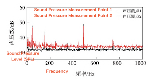
Fig. 9 Sound pressure level (SPL) spectra of background noise at the two measurement points
The experimental data were processed using the short-time Fourier transform (STFT). The resulting time–frequency spectra were analyzed to determine whether the experimental system had reached a stable operating state. Figure 10 shows the STFT results for the entire data set and the selected valid data segment. As shown in Fig. 10, the spectral characteristics and amplitudes within the selected segment remain essentially stable over time, and the segment is sufficiently long to support reliable spectral analysis. Multiple repeated trials were also conducted to further ensure the reliability and validity of the experimental results.
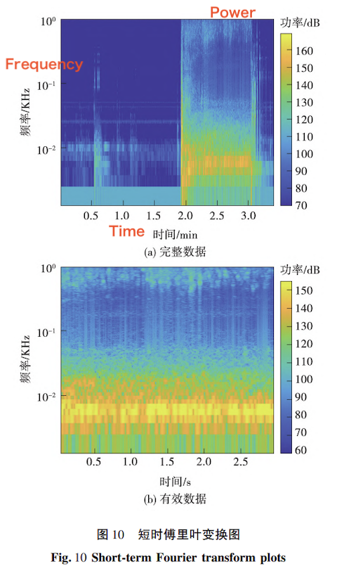
(a) Complete data set (b) Valid data segment
Fig. 10 Short-Time Fourier Transform (STFT) plots
Based on the noise reduction principles of porous media, this study proposes a wall-mounted porous-medium structure for controlling flow-induced noise in a large-diameter pipe bend downstream of two butterfly valves arranged at 180°. The noise reduction mechanism of the porous medium was investigated through numerical simulations. A high-pressure, gas-driven water-flow test rig was constructed, and the porous-medium control structures were fabricated for experimental validation. Comparative tests were conducted under different operating conditions. The main conclusions are as follows:
(1) The proposed porous-medium control scheme effectively reduces pressure fluctuations on the elbow wall and weakens dipole sound sources. It provides a practical approach to controlling flow-induced noise in pipe bends downstream of butterfly valves.
(2) Based on extensive numerical simulations and experimental tests, the proposed porous-medium control scheme achieves its best noise reduction performance at Re = 7.8 × 10⁵. The reported reduction in the overall sound pressure level over the 10–1,000 Hz frequency band is 8.52 dB, indicating its potential for broader engineering applications.