Abstract: Concentric butterfly valves are widely used in the chemical industry. To investigate their flow resistance characteristics, a dedicated test rig was developed, and experimental tests were conducted on DN70 and DN80 valves. Numerical simulations were performed to analyze the flow fields of butterfly valves with different diameters and establish the relationship between valve opening and the flow resistance coefficient. Curve fitting was then used to derive expressions relating valve opening to the resistance coefficient for four valve sizes. Both experimental and numerical results show that the optimal valve opening range for flow regulation is 20°–40°. These findings provide a theoretical basis for flow regulation and valve installation in process piping systems in chemical plants.
Butterfly valves are widely used because of their simple operation, low cost, and good flow-regulation performance. In chemical plant process piping systems, they are commonly used to regulate media such as cooling water, chilled water, oxygen, air, nitrogen, liquid air, liquid oxygen, and liquid nitrogen. Research on butterfly valves in China and abroad has mainly focused on their hydraulic characteristics and mechanical performance. Although recent studies have investigated valve regulation in heating and water supply networks, most have focused on flow characteristics rather than the functional relationship between valve opening and the flow resistance coefficient for different valve diameters. Building on previous research, this study focuses on establishing the relationship between valve opening and the flow resistance coefficient for butterfly valves of different diameters and determining the optimal opening range for flow regulation in process piping systems.
This study investigates the hydraulic characteristics of industrial butterfly valves through a combination of numerical simulation and experimental testing. A dedicated flow resistance test rig was developed to conduct experiments under multiple operating conditions using DN70 and DN80 butterfly valves. Computational fluid dynamics (CFD) was then used to establish three-dimensional flow field models. After the simulation model was validated against the experimental results, the analysis was extended to DN100 and DN125 butterfly valves. The relationship between valve opening and the flow resistance coefficient was systematically analyzed for butterfly valves with different nominal diameters, providing a theoretical basis for optimizing flow control in industrial piping systems.
As a core process system in the chemical industry, an air separation unit (ASU) is primarily used for the large-scale production of oxygen, nitrogen, and argon. Its process configuration integrates molecular sieve-based air purification, multistage compression, and full-distillation argon extraction. The system employs a thermodynamic cycle with a booster medium-pressure turbo-expander and a rectification configuration in which the upper and lower columns are connected through expanded air and the rectification column uses structured packing. This configuration offers significant advantages in operational stability, energy efficiency, and ease of operation. Within the ASU, butterfly valves play a critical role in flow regulation and are widely used in key systems, including air separation, cryogenic medium transport, and circulating water systems.
During operation, liquid products are continuously discharged through a dual-line storage system. Liquid oxygen from the atmospheric storage tanks is pressurized by high-pressure pumps and vaporized in a vaporization heat exchanger, while liquid nitrogen is pressurized and vaporized by dedicated pump units, forming a complete two-line product supply process. To address flow imbalances in air separation piping networks, distributed control systems (DCS) are typically used for real-time monitoring and diagnosis. When hydraulic imbalance is detected in a specific pipeline section, fluid dynamic models are used to calculate the target flow resistance parameters, allowing precise adjustment of the butterfly valve opening. However, because the relationship between valve opening and the flow resistance coefficient is nonlinear and varies with pipe diameter, conventional flow regulation methods may suffer from response delays and inadequate balancing accuracy. Therefore, this study develops a valve flow resistance prediction method that accounts for different pipe diameters, providing a theoretical basis for achieving hydraulic balance in complex piping networks.
A test rig for evaluating the flow resistance of butterfly valves was constructed, as shown in Figure 1(a). The rig can be used to measure the resistance characteristics of various valve types, including butterfly, ball, and globe valves. In this study, flanged concentric butterfly valves with nominal diameters of DN70 and DN80 were tested.
The test rig uses an elevated water tank to maintain a constant water pressure. During operation, a circulating pump delivers water from the tank into the test pipeline. The water then passes through the differential pressure transmitter for the upstream straight-pipe section, the test valve, a flow meter, and a downstream regulating valve before returning to the tank. The pressure drop across the test valve is measured using a separate differential pressure transmitter. The differential pressure and flow rate are displayed on the corresponding instrument panels.
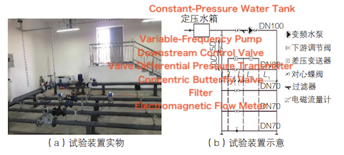
(a) Photograph of the test apparatus (b) Schematic of the test apparatus
Figure 1. Test apparatus for measuring valve flow resistance
In designing the test apparatus, the lengths of L₁–L₅, the pipe dimensions, and the height of the constant-pressure water tank were determined in accordance with GB/T 30832—2014, Valves—Test Method of Flow Coefficient and Flow Resistance Coefficient. To ensure measurement accuracy, the differential pressure transmitters used to measure the pressure drop across the test valve were installed at locations satisfying L₃ > 5D and L₄ > 10D, where D is the nominal pipe diameter. The differential pressure transmitter for the straight-pipe section was installed such that L₂ = L₃ + L₄. According to the electromagnetic flow meter manufacturer's instructions, the upstream straight-pipe length was set to more than 10D, while the downstream straight-pipe length was set to more than 5D.
- Before testing, flush the pipeline with clean water at a flow velocity of at least 1.5 m/s. Continue flushing until the water discharged from the outlet is visually identical to that at the inlet, confirming that the pipeline is free of impurities that could affect the instrument readings.
- The test platform uses a four-channel parallel configuration. When one channel is selected for valve flow resistance testing, the valves in the other three channels must remain fully closed to eliminate bypass flow and prevent it from affecting the differential pressure measurements.
- An air vent is installed at the highest point of the piping system. The circulating water pump is switched on and operated until water flows from the vent, ensuring that no air remains in the pipeline that could affect the test results. The opening angle of the test valve is then set sequentially to 90°, 65°, 50°, 40°, 35°, 30°, 25°, and 20°, with 90° corresponding to the fully open position of the butterfly valve.
- After the valve is adjusted to the preset opening and remains stable for 10 s, the real-time readings of the electromagnetic flow meter are monitored. If the readings remain within the allowable error range, the maximum and minimum values recorded during this period are obtained. When the deviation of both the maximum and minimum values from the mean does not exceed 1.2% of the mean, the flow rate and differential pressure data for the test valve are recorded. During the test, flow rate and differential pressure data are collected simultaneously at intervals of at least 5 s. At least five valid data sets are obtained under each operating condition, and the arithmetic mean is taken as the final result.
- To eliminate the effect of the piping system's own flow resistance, the pressure drops across the upstream and downstream straight-pipe sections are measured simultaneously. The test conditions and procedures are the same as those used for the valve test. Specifically, while the differential pressure across the valve is being recorded, the pressure drop across the straight-pipe section (L₂) is measured using the same procedure.
- After the test is completed, open the drain valve, switch off the circulating water pump, and disconnect the power supply.
The net pressure drop across the test valve is obtained by subtracting the pressure drop across the straight-pipe section from the total pressure drop across the valve test section. The flow resistance coefficient is calculated using Equation (1):
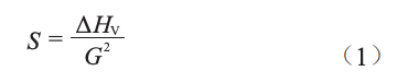
Where: S — flow resistance coefficient of the valve, Pa/(m³/h)²;
Δ HV — net pressure drop across the valve, Pa;
G — flow rate through the valve test pipeline, m³/h.
The relationship between valve opening angle and the flow resistance coefficient is shown in Figure 2.
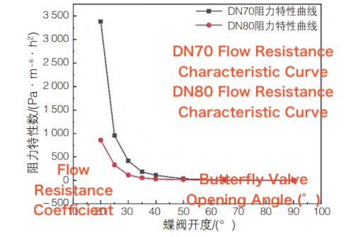
Figure 2. Flow resistance characteristic curves of DN70 and DN80 butterfly valves
Table 1. Test Data for DN70 and DN80 Butterfly Valves
Valve Opening (°) | DN70 Flow Rate (m³/h) | DN70 Net Pressure Drop (kPa) | DN70 Flow Resistance Coefficient (Pa·h²/m⁶) | DN80 Flow Rate (m³/h) | DN80 Net Pressure Drop (kPa) | DN80 Flow Resistance Coefficient (Pa·h²/m⁶) |
20 | 5.29 | 94.68 | 3383.34 | 10.11 | 87.64 | 857.43 |
25 | 9.58 | 87.78 | 956.45 | 15.07 | 75.35 | 331.79 |
30 | 13.61 | 77.31 | 417.36 | 20.69 | 49.64 | 115.96 |
35 | 18.18 | 60.94 | 184.38 | 23.62 | 31.69 | 56.80 |
40 | 20.59 | 46.78 | 110.34 | 25.28 | 19.77 | 30.94 |
50 | 24.64 | 22.16 | 36.49 | 26.16 | 13.45 | 19.65 |
65 | 26.43 | 6.36 | 9.10 | 27.41 | 3.33 | 4.43 |
90 | 27.01 | 4.05 | 5.55 | 27.42 | 2.16 | 2.87 |
Analysis of the test data for the DN70 butterfly valve (Figure 2 and Table 1) shows that when the valve is fully open (90°), the flow resistance coefficient is only 5.55 Pa/(m³/h)², and the net pressure drop is 4.05 kPa. At this point, the butterfly valve has essentially lost its throttling capability. As the opening angle decreases from 90° to 40°, the net pressure drop increases significantly to 46.78 kPa, representing a 10.5-fold increase. However, the flow rate does not decrease linearly with the opening angle, resulting in only a gradual increase in the flow resistance coefficient over this range. When the opening angle reaches 20°, the flow resistance coefficient increases sharply. For every 5° decrease in the opening angle, the flow resistance coefficient rises substantially. Tests also show that when the opening angle decreases below 15° and approaches 10°, the flow meter reading drops to zero, indicating that the valve is fully closed.
In the 50°–90° opening range, the difference in the flow resistance coefficient between the two valve sizes remains within ±8%, indicating similar flow resistance characteristics. In the 20°–40° opening range, however, the nominal valve diameter has a significant effect on flow resistance. The flow resistance coefficient of the DN70 valve is, on average, 2.3–3.1 times that of the DN80 valve, indicating that a smaller nominal diameter results in substantially higher local flow resistance.
Experimental results indicate that the butterfly valve operates within three distinct ranges:
① Ineffective range (40°–90°): The sensitivity of the flow resistance coefficient is low, and the butterfly valve provides little throttling effect within this range.
② Oversensitive range (0°–20°): The valve exhibits poor control stability, and small changes in the opening angle cause sharp variations in flow rate.
③ Effective operating range (20°–40°): The valve provides relatively good linear regulation with moderate sensitivity, making this range suitable for flow distribution control in process piping systems.
Based on the turbulent flow characteristics commonly encountered in industrial piping systems, the standard k–ε two-equation turbulence model was employed to analyze the three-dimensional flow field of the butterfly valve. The continuity and momentum equations were formulated within the Navier–Stokes framework under the following assumptions:
- The computational domain was constructed based on the inner diameter of the pipe, and the internal geometry of the butterfly valve was simplified by removing components such as the valve stem.
- Gravitational and buoyancy effects were neglected, and the flow was assumed to be isothermal.
- The fluid was assumed to be an incompressible Newtonian fluid with constant density.
Continuity equation:

where uₓ, uy, and u z are the velocity components in the x, y, and z directions, respectively,in (m/s).
Momentum conservation equation:
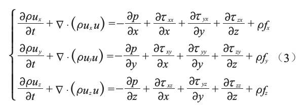
Where P — pressure of the fluid element;
τ — viscous stress component;
f — body force per unit mass in the x, y, and z directions.
ANSYS Fluent was used to investigate the flow field characteristics of the DN70 and DN80 butterfly valves. The total length of the computational domain was set to 20 times the pipe diameter (L = 20D), with an upstream extension of L₁ = 10D and a downstream extension of L₂ = 10D, ensuring that the boundary conditions had a negligible effect on the internal flow field. The butterfly disc was designed strictly according to the equal-diameter principle, with its effective diameter equal to the nominal pipe diameter (1:1 ratio). Eight representative opening angles were selected for the analysis: 20°, 25°, 30°, 35°, 40°, 50°, 65°, and 90°. A computational model was then constructed for each opening angle. Figure 3 shows the three-dimensional model of the DN70 butterfly valve at an opening angle of 35°.

Figure 3. Three-dimensional model of the butterfly valve flow passage
To improve the accuracy of the butterfly valve flow field simulation, a zonal meshing strategy was adopted to discretize the three-dimensional flow passage model of the DN70 valve at a 35° opening angle. As shown in Figure 4, the computational domain was divided into five subregions based on the flow characteristics. A tetrahedral mesh with a mesh size of 10 mm was used in the relatively stable inlet and outlet regions to improve computational efficiency. In the transition region adjacent to the valve body, the mesh size was reduced to 6 mm to better capture flow field gradients. In the critical regions upstream and downstream of the valve disc, a finer 2 mm surface mesh combined with tetrahedral elements was used to resolve the flow details. A total of 733,112 unstructured elements and 141,235 nodes were generated throughout the computational domain, providing a balance between computational efficiency and simulation accuracy.

Figure 4. Mesh generation for the butterfly valve flow passage model
- The inlet boundary condition was specified as a velocity inlet. The flow direction was aligned with the +z axis, with the velocity components in the x and y directions set to zero and the inlet velocity set to 1 m/s.
- The outlet boundary condition was specified as an outflow.
- The pipe wall and valve disc surfaces were specified as no-slip walls.
- The working fluid was defined as liquid water.
The DN70 butterfly valve was selected as an example for analysis. The velocity vector field inside the butterfly valve obtained from the numerical simulation is shown in Figure 5. At an opening angle of 20°, the fluid entering at 1 m/s forms a high-speed jet downstream of the valve, with a peak velocity of 21 m/s, equivalent to 21 times the inlet velocity. Large-scale vortices also develop downstream of the valve disc, and the associated turbulent energy dissipation contributes to the increased flow resistance. As the opening angle increases to 40°, the peak velocity decreases to 8.3 m/s, accompanied by a reduction in vortex size. In the 65°–90° opening range, the flow field becomes relatively uniform, and the thickness of the valve disc can be regarded as the primary factor responsible for boundary-layer separation.
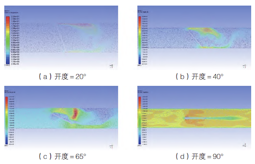
(a) Opening Angle = 20° (b) Opening Angle = 40° (c) Opening Angle = 65° (d) Opening Angle = 90°
Figure 5. Velocity vector field near the valve disc in the x–z plane
The pressure contour in Figure 6 shows that at an opening angle of 20°, the upstream pressure reaches 474.9 kPa, while a negative gauge pressure of −71 kPa develops downstream of the valve, resulting in a pressure drop of 471.6 kPa. This indicates that the butterfly valve provides strong throttling at this opening angle. At an opening angle of 40°, the pressure drop decreases to 17.8 kPa. In the 65°–90° opening range, the pressure distribution becomes nearly symmetrical, and the pressure drop varies by less than 2 kPa, indicating that the valve has limited flow-regulation capability in this range. Based on the pressure and velocity field analyses, the effective flow-regulation range of the DN70 butterfly valve is 20°–40°.
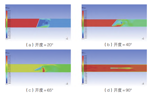
(a) Opening angle = 20° (b) Opening angle = 40° (c) Opening angle = 65° (d) Opening angle = 90°
Figure 6. Pressure distribution near the butterfly valve disc in the x–z plane
By substituting the numerical simulation data for the DN70 and DN80 butterfly valves into Equation (1), the flow resistance coefficients at different opening angles were calculated. The numerical results were compared with the experimental data, as shown in Figure 7. The two sets of results are in good agreement, confirming the reliability of the numerical model. However, slight discrepancies in the flow resistance coefficients are observed at small opening angles. These discrepancies are attributed to the simplified internal geometry used in the numerical model, which does not account for the effects of the valve stem and sealing structure on the flow field.
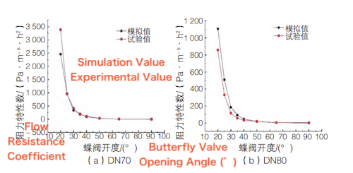
Figure 7. Comparison of measured and simulated flow resistance coefficients for the butterfly valves
A comparative study was conducted under four inlet flow velocity conditions, ranging from 1.0 to 4.0 m/s. Figure 8 shows that although the volumetric flow rate and pressure drop across the valve increased approximately linearly with the inlet flow velocity, the flow resistance coefficients remained nearly constant after normalization, with deviations of less than ±2%. This behavior is consistent with the principle of dynamic similarity in fluid flow, indicating that the flow resistance characteristics of the butterfly valve are primarily determined by its geometric opening angle and are essentially independent of the flow velocity.
The numerical model was validated by comparing the simulation results with the experimental data. Owing to limitations in test conditions and cost, physical experiments could not cover all commonly used pipe diameter specifications. Therefore, CFD simulations were performed to extend the investigation to DN100 and DN125 butterfly valves.
For the DN100 and DN125 butterfly valves, the flow passage models were constructed following the method described in Section 3.2, using boundary conditions and meshing strategies consistent with those applied to the DN70 model. After the flow parameters at various opening angles were obtained through CFD simulations, the corresponding flow resistance coefficients were calculated using Equation (1). Figure 8 presents the flow resistance characteristic curves for butterfly valves with different nominal diameters. The results show that butterfly valves with different nominal diameters exhibit similar trends in flow resistance. At large opening angles (50°–90°), the resistance coefficients differ only slightly among the different valve sizes because the larger flow area results in relatively low flow resistance. In contrast, within the flow-regulation range of 20°–50°, the resistance coefficient increases significantly as the opening angle decreases. Moreover, at the same opening angle, the resistance coefficient decreases as the nominal diameter increases. These results indicate that nominal diameter has a significant effect on the flow resistance characteristics. Accordingly, in practical engineering applications, the flow resistance characteristic curve corresponding to the specific valve size should be selected for flow regulation.
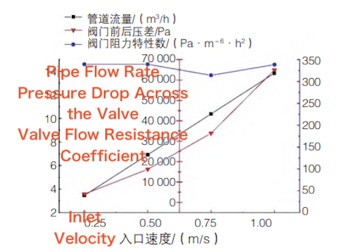
Figure 8. Schematic of the valve and pipe section parameters
Curve fitting was performed on the data shown in Figure 9. The results show that the flow resistance characteristics of the butterfly valves can be well described by a single exponential decay function. The corresponding mathematical model is given by Equation (4):

where S is the flow resistance coefficient of the valve, Pa/(m³/h)²; K is the valve opening angle, °; and A, t, and CC are fitted coefficients.
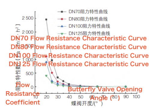
Figure 9. Flow resistance characteristic curves for butterfly valves with four different nominal diameters
- Both experimental and numerical results indicate that the throttling effect and flow resistance coefficient of the butterfly valve increase as the opening angle decreases. The 40°–90° range represents the ineffective control range, in which the valve provides little throttling effect. The 0°–20° range represents the oversensitive control range, in which small changes in the opening angle cause sharp variations in flow resistance and flow rate, resulting in poor control stability. The 20°–40° range represents the effective regulation range, in which effective flow control can be achieved. For the larger nominal diameters (DN100 and DN125), the effective regulation range shifts slightly compared with that of the smaller diameters, extending to 10°–40°.
- Functional relationships between the valve opening angle and flow resistance coefficient were established by curve fitting for four nominal diameters. These relationships provide a theoretical basis for the design and operational control of process piping systems.