
Optimal Design of Sealing Pairs of Wedge Gate Valves with Large Diameters (Part One)
The structure and working characteristics of sealing pairs of wedge gate valves with large diameters are discussed in this article. Structure of sealing pairs of wedge electric gate valves with DN1200 is designed and analyzed, and the size is reasonably optimized according to the actual needs. The results show that the design can fully meet the requirement for the actual strength.
1. Overview
A gate valve is the most common valve in industrial applications. The working principle of a gate valve is that the valve plate moves along the direction perpendicular to the valve body channel under the action of the power source. It is used to cut off the medium in the conveying pipeline, that is, being fully opened or fully closed, which has reliable sealing performance. The fluid resistance of a gate valve is small, and the flow resistance of the medium passing through the channel of the gate valve body is close to 0. A gate valve is a two-way valve with two-way flows. The flow direction of the medium in the valve body channel is not restricted. The medium can flow through the two sides of the gate valve without affecting the normal opening and closing of the gate valve. Therefore, a gate valve is suitable for pipelines where the flow direction of the medium may change.
2. Working principles
The wedge gate valve with large diameters is mainly composed of a valve body, a valve bonnet, a valve seat, a valve plate, a valve stem, and an electric device (Figure 1). The electric drive is the power source of the valve. When the valve is opened, the electric transmission device rotates forward, and the valve plate is moved vertically upwards along the channel through the valve stem and valve stem nut's transmission pair. When the preset opening height of the valve is reached, the electric transmission device stops driving and the valve reaches the open state. When the valve is closed, the electric transmission device rotates in the opposite direction, and the valve plate is moved vertically down along the channel through the valve stem and valve stem nut's transmission pair. When the preset closing height of the valve is reached, the electric transmission device stops driving and the valve reaches the closed state.
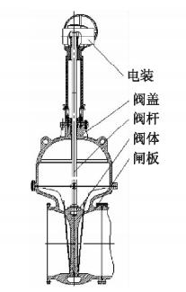
1. Electric devices 2. Valve bonnets 3. Valve stems 4. Valve bodies 5. Valve plates
Figure 1 The structure of wedge gate valves
3. The structural design of sealing pairs
The structure and key dimensions of the valve body and plate of the wedge-type electric gate valve of DN 1200 mm and PN 1.0MPa are designed and optimized in this article.
3.1 The structure of the valve body
3.1.1 The size of the middle cavity
The valve body is made by integral casting (Figure 2); the upper flange is designed as a circular structure, and the inner cavity of the upper flange of the valve body is provided with reinforcing ribs. The middle valve body cavity is deformed and makes the sealing surface deform excessively and cause leakages. Therefore, horizontally and longitudinal reinforcing ribs are arranged at different positions on the inner wall of the valve body cavity to limit the deformation of the valve body. Two horizontal and three longitudinal reinforcing ribs are arranged on the upper part of the inner wall of the valve body cavity. This structure is uniformly stressed and not easily deformed. The lower end of the valve body is designed to be oblate, and the valve body and valve seat have an integrated structure design. WCB is selected for the material of the valve body. The surface of the valve seat is welded with hard alloys to improve its wear resistance and scratch resistance.
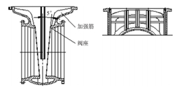
Figure 2 The structure of the valve body
Calculate the wall thickness t of the valve body, and formula (1) is obtained.
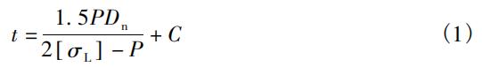
In the formula, T is the wall thickness of the valve body, mm. P means the design pressure, MPa.
Dn is the inner diameter of the valve body's middle cavity, mm. C means the corrosion allowance, mm. [σL] is the allowable tension pressure of the valve body's material, MPa.
Among them, the design pressure is 1.0 MPa; the inner diameter of the valve body cavity is 1300 mm; the corrosion allowance C is 5 mm, and the allowable tension pressure [σL] of the valve body's material is 82MPa. The wall thickness is 17 mm after calculation. The actual wall thickness is 25 mm to ensure design redundancy.
3.1.2 The wedge angle of the valve body and seat
There is a certain inclination angle between the sealing surface of the wedge gate valve seat and the center line of the vertical channel. The commonly used wedge half angles are 2° and 5°. The size of the wedge half-angle has an important influence on the performance of the gate valve. When the angle is small, the force required to close the gate valve is small. However, when the pipeline is deformed due to temperature changes, the possibility of the wedge-shaped plate being wedged in the valve body increases. Therefore, the sealing surface with a wedge angle of 5° is selected for the valve seat.
3.2 The structure of the valve plate
3.2.1 Structural selection
The valve plate is another key component, which plays an important role in the opening and closing of the valve. In the closed state, the valve plate needs to withstand the pressure of about 1.0MPa from the incoming medium, and almost no force when the medium flows. Therefore, the valve plate is prone to deformation. There are strict requirements on the strength and rigidity of the valve plate, and it is required to have good sealing performance and good reliability.
A wedge-type with 5° double valve plate structure is mostly used for sealing pairs of wedge gate valves with large diameters, which are composed of two valve plates (Figure 3). A wedge-shaped plate connected by a spherical center hinge can freely adjust the angle to match with the valve seat at the two sides. The sealing wedge angle of the valve plate can be automatically adjusted by the hinged top center spherical surface, so the accuracy of the angle of the plate's sealing surface is low. It is not easy to be stuck when the temperature changes, and scratches won't easily happen. After the sealing surface of the valve plate is worn, a gasket can be added to the top center to compensate for easy maintenance. At the same time, it reduces the possibility of wedging of the plate when the temperature rises. However, there are also disadvantages such as complex structure, large sizes, many structural parts, loos structure, poor reliability, the valve plate being easy to fall off, failures like relief grooves or pin holes at the root of the valve stem being broken, valve plates falling off due to the rusted upper and lower baffles and grillage being broken, which are not suitable for viscous media.

Figure 3 Wedge double plates
In view of the shortcomings of wedge double plates, the electric wedge plate with DN 1200 mm adopts a wedge elastic plate structure (Figure 4), with an annular groove on the vertical midplane, and the annular groove has a certain flexibility. When the valve is closed, the slight deformation of the valve plate can compensate for the matching gap with the valve seat due to manufacturing deviations, so that the sealing surface of the valve plate at the two sides and the valve seat are completely matched. At the same time, a sealing specific pressure is formed to achieve the purpose of sealing. When the temperature of the medium changes, the valve plate is not easy to be jammed. The closing torque should not be too great and the elastic deformation range of the valve plate should not be exceeded. The wedge-type elastic plate has a simple structure, and the processing accuracy of the wedge angle is relatively low. It is not easy to get stuck when the temperature of the medium changes. This structure is more compact and lighter than the wedge-type double plate, thus reducing the overall size and weight of the valve.
1. Overview
A gate valve is the most common valve in industrial applications. The working principle of a gate valve is that the valve plate moves along the direction perpendicular to the valve body channel under the action of the power source. It is used to cut off the medium in the conveying pipeline, that is, being fully opened or fully closed, which has reliable sealing performance. The fluid resistance of a gate valve is small, and the flow resistance of the medium passing through the channel of the gate valve body is close to 0. A gate valve is a two-way valve with two-way flows. The flow direction of the medium in the valve body channel is not restricted. The medium can flow through the two sides of the gate valve without affecting the normal opening and closing of the gate valve. Therefore, a gate valve is suitable for pipelines where the flow direction of the medium may change.
2. Working principles
The wedge gate valve with large diameters is mainly composed of a valve body, a valve bonnet, a valve seat, a valve plate, a valve stem, and an electric device (Figure 1). The electric drive is the power source of the valve. When the valve is opened, the electric transmission device rotates forward, and the valve plate is moved vertically upwards along the channel through the valve stem and valve stem nut's transmission pair. When the preset opening height of the valve is reached, the electric transmission device stops driving and the valve reaches the open state. When the valve is closed, the electric transmission device rotates in the opposite direction, and the valve plate is moved vertically down along the channel through the valve stem and valve stem nut's transmission pair. When the preset closing height of the valve is reached, the electric transmission device stops driving and the valve reaches the closed state.
1. Electric devices 2. Valve bonnets 3. Valve stems 4. Valve bodies 5. Valve plates
Figure 1 The structure of wedge gate valves
3. The structural design of sealing pairs
The structure and key dimensions of the valve body and plate of the wedge-type electric gate valve of DN 1200 mm and PN 1.0MPa are designed and optimized in this article.
3.1 The structure of the valve body
3.1.1 The size of the middle cavity
The valve body is made by integral casting (Figure 2); the upper flange is designed as a circular structure, and the inner cavity of the upper flange of the valve body is provided with reinforcing ribs. The middle valve body cavity is deformed and makes the sealing surface deform excessively and cause leakages. Therefore, horizontally and longitudinal reinforcing ribs are arranged at different positions on the inner wall of the valve body cavity to limit the deformation of the valve body. Two horizontal and three longitudinal reinforcing ribs are arranged on the upper part of the inner wall of the valve body cavity. This structure is uniformly stressed and not easily deformed. The lower end of the valve body is designed to be oblate, and the valve body and valve seat have an integrated structure design. WCB is selected for the material of the valve body. The surface of the valve seat is welded with hard alloys to improve its wear resistance and scratch resistance.
Figure 2 The structure of the valve body
Calculate the wall thickness t of the valve body, and formula (1) is obtained.
In the formula, T is the wall thickness of the valve body, mm. P means the design pressure, MPa.
Dn is the inner diameter of the valve body's middle cavity, mm. C means the corrosion allowance, mm. [σL] is the allowable tension pressure of the valve body's material, MPa.
Among them, the design pressure is 1.0 MPa; the inner diameter of the valve body cavity is 1300 mm; the corrosion allowance C is 5 mm, and the allowable tension pressure [σL] of the valve body's material is 82MPa. The wall thickness is 17 mm after calculation. The actual wall thickness is 25 mm to ensure design redundancy.
3.1.2 The wedge angle of the valve body and seat
There is a certain inclination angle between the sealing surface of the wedge gate valve seat and the center line of the vertical channel. The commonly used wedge half angles are 2° and 5°. The size of the wedge half-angle has an important influence on the performance of the gate valve. When the angle is small, the force required to close the gate valve is small. However, when the pipeline is deformed due to temperature changes, the possibility of the wedge-shaped plate being wedged in the valve body increases. Therefore, the sealing surface with a wedge angle of 5° is selected for the valve seat.
3.2 The structure of the valve plate
3.2.1 Structural selection
The valve plate is another key component, which plays an important role in the opening and closing of the valve. In the closed state, the valve plate needs to withstand the pressure of about 1.0MPa from the incoming medium, and almost no force when the medium flows. Therefore, the valve plate is prone to deformation. There are strict requirements on the strength and rigidity of the valve plate, and it is required to have good sealing performance and good reliability.
A wedge-type with 5° double valve plate structure is mostly used for sealing pairs of wedge gate valves with large diameters, which are composed of two valve plates (Figure 3). A wedge-shaped plate connected by a spherical center hinge can freely adjust the angle to match with the valve seat at the two sides. The sealing wedge angle of the valve plate can be automatically adjusted by the hinged top center spherical surface, so the accuracy of the angle of the plate's sealing surface is low. It is not easy to be stuck when the temperature changes, and scratches won't easily happen. After the sealing surface of the valve plate is worn, a gasket can be added to the top center to compensate for easy maintenance. At the same time, it reduces the possibility of wedging of the plate when the temperature rises. However, there are also disadvantages such as complex structure, large sizes, many structural parts, loos structure, poor reliability, the valve plate being easy to fall off, failures like relief grooves or pin holes at the root of the valve stem being broken, valve plates falling off due to the rusted upper and lower baffles and grillage being broken, which are not suitable for viscous media.
Figure 3 Wedge double plates
In view of the shortcomings of wedge double plates, the electric wedge plate with DN 1200 mm adopts a wedge elastic plate structure (Figure 4), with an annular groove on the vertical midplane, and the annular groove has a certain flexibility. When the valve is closed, the slight deformation of the valve plate can compensate for the matching gap with the valve seat due to manufacturing deviations, so that the sealing surface of the valve plate at the two sides and the valve seat are completely matched. At the same time, a sealing specific pressure is formed to achieve the purpose of sealing. When the temperature of the medium changes, the valve plate is not easy to be jammed. The closing torque should not be too great and the elastic deformation range of the valve plate should not be exceeded. The wedge-type elastic plate has a simple structure, and the processing accuracy of the wedge angle is relatively low. It is not easy to get stuck when the temperature of the medium changes. This structure is more compact and lighter than the wedge-type double plate, thus reducing the overall size and weight of the valve.
