
Optimal Design of Sealing Pairs of Wedge Gate Valves with Large Diameters (Part Two)
3.2.2 The size of the wedge
The wedge is made from WCB, which is the same as the valve body and is integrally casted (Figure 4). Calculate the thickness tB of the wedge, and get the following formula:
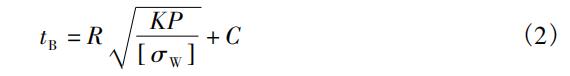
In the formula, tB is the thickness of the wedge (mm). R is the average radius of the sealing surface of the wedge (mm). K is the safety factor. Among them, the design pressure is 1.0MPa. The average radius R of the wedge's sealing surface is 560 mm. The safety factor K is 1.24. The corrosion allowance C is 5 mm, and the allowable bending stress [σw] of the wedge's material is 102MPa. The thickness of the wedge is 66 mm. In order to ensure the designed redundancy, 70 mm is adopted.
The elastic characteristics of the elastic wedge mainly depend on the elastic ratio m, namely
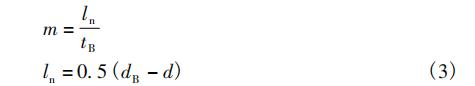
In the formula, dB is the transition diameter of elastic deformation of the wedge (mm). D means the bottom diameter of the elastic groove (mm). Among them, the thickness tB of the wedge is 70 mm; the transition diameter of elastic deformation of the wedge is 1040 mm, and the bottom diameter d of the elastic groove is 600 mm. The elastic ratio of the wedge is calculated to be 3.14. If the elasticity ratio is too small, it will be unfavorable to the elastic deformation of the wedge, which will affect the fitness of the sealing surface and result in poor sealing performance of the valve. For the gate valve with a nominal diameter of 1200 mm, its elastic deformation ratio is not specified in the current standard. The gate valve with a nominal diameter of 1000 mm whose deformation ratio m is 3 can be used.
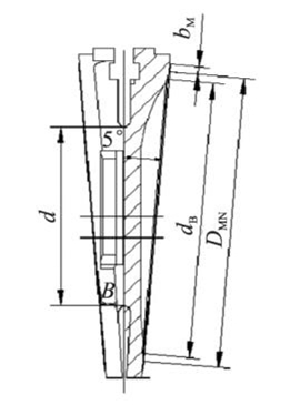
Figure 4 The structure of the wedge
4. The analysis and verification of the sealing structure
In order to verify the structural design and performance of the large-diameter wedge gate valve's sealing pairs, the finite element numerical simulation method is used to calculate the deformation of the valve body and the wedge under the test load.
4.1 Establishing a geometric model and setting properties of materials
Three-dimensional modeling is carried out based on the above calculation results of the valve body and the sealing substructure of the wedge, and the built three-dimensional model is input into the analysis software. The material of the valve body and wedge is WCB, and the material properties of the finite element analysis model are set according to the parameters in Table 1.
Table 1 Parameters of materials and characteristics
The wedge is made from WCB, which is the same as the valve body and is integrally casted (Figure 4). Calculate the thickness tB of the wedge, and get the following formula:
In the formula, tB is the thickness of the wedge (mm). R is the average radius of the sealing surface of the wedge (mm). K is the safety factor. Among them, the design pressure is 1.0MPa. The average radius R of the wedge's sealing surface is 560 mm. The safety factor K is 1.24. The corrosion allowance C is 5 mm, and the allowable bending stress [σw] of the wedge's material is 102MPa. The thickness of the wedge is 66 mm. In order to ensure the designed redundancy, 70 mm is adopted.
The elastic characteristics of the elastic wedge mainly depend on the elastic ratio m, namely
In the formula, dB is the transition diameter of elastic deformation of the wedge (mm). D means the bottom diameter of the elastic groove (mm). Among them, the thickness tB of the wedge is 70 mm; the transition diameter of elastic deformation of the wedge is 1040 mm, and the bottom diameter d of the elastic groove is 600 mm. The elastic ratio of the wedge is calculated to be 3.14. If the elasticity ratio is too small, it will be unfavorable to the elastic deformation of the wedge, which will affect the fitness of the sealing surface and result in poor sealing performance of the valve. For the gate valve with a nominal diameter of 1200 mm, its elastic deformation ratio is not specified in the current standard. The gate valve with a nominal diameter of 1000 mm whose deformation ratio m is 3 can be used.
Figure 4 The structure of the wedge
4. The analysis and verification of the sealing structure
In order to verify the structural design and performance of the large-diameter wedge gate valve's sealing pairs, the finite element numerical simulation method is used to calculate the deformation of the valve body and the wedge under the test load.
4.1 Establishing a geometric model and setting properties of materials
Three-dimensional modeling is carried out based on the above calculation results of the valve body and the sealing substructure of the wedge, and the built three-dimensional model is input into the analysis software. The material of the valve body and wedge is WCB, and the material properties of the finite element analysis model are set according to the parameters in Table 1.
Table 1 Parameters of materials and characteristics
| Parts | Materials | Elastic modulus/MPa | Density/(kg/m3) | Poisson's ratio | Yield strength/MPa | Tensile strength/MPa |
| Valve bodies or wedges | WCB | 2.02 x 10⁵ | 7850 | 0.31 | 248 | 483 |
4.2 The finite element analysis of the valve body
4.2.1 Meshing division
Mesh division is an important part of the finite element analysis process. In the finite element calculation, only the nodes and elements of the mesh participate in the calculation. The density of the mesh directly affects the accuracy of the calculation results, but the refined mesh will increase the CPU's calculation time and storage space. Ideally, the mesh density required by the user is the density whose result does not change with the refinement of the mesh, that is, when the mesh is refined, the solution does not change significantly. The valve body is divided by tetrahedral meshes. The meshing model is shown in Figure 5. It contains 1132651 nodes and 753671 elements. The average quality of the elements is 0.815 and the orthogonal quality is 0.843. The mesh quality is good.
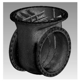
Figure 5 Meshing of the valve body
4.2.2 Constraints and boundary conditions
The simulation calculation is that when the gate valve is closed, the sealing test pressure is 1.1MPa loaded into the cavity.
The sealing force FM on the valve sealing surface is as the following:

Among them, take DMN 1100 mm, bM 20 mm, qMF 3.2MPa, and calculate FM to be 225kN. The valve body is also affected by the gravity of the valve bonnet and electric fitting part, which is about 20kN. Constraints and boundary conditions are conducted for the valve body, as shown in Figure 6.
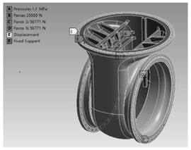
Figure 6 Constraints and boundary conditions of valve bodies
4.2.3 The solving process
After determining the boundary conditions imposed by the valve body, the finite element model of the valve body is solved, and the deformation cloud picture of the valve body is obtained as shown in Figure 7.
4.3 The finite element analysis of the wedge
The finite element analysis process of the wedge is the same as that of the valve body. The finite element model is shown in Figure 8, including a total of 511544 nodes and 3480919 elements, among which the average quality of units is 0.826 and the orthogonal quality is 0.852. The quality of the grid divided by the wedge is good.
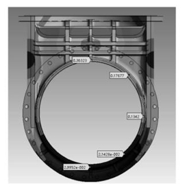
Figure 7 The cloud picture of the deformation of the valve body
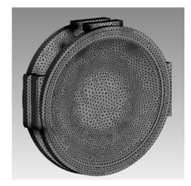
Figure 8 Mesh division of the wedge
In the wedge, friction is generated between the sealing surface of the wedge and valve body at both inlets and outlets of the medium. The friction between the wedge and valve body guide rail and as well as sealing surface of the wedge and valve body cannot work at the same time, so only one of them is considered in the calculation; the latter calculation result is used here. Since the gravity of the parts mounted on the valve stem is smaller than the sealing force acting on the wedge, its value is negligible. After determining the boundary conditions imposed on the wedge, the finite element model of the wedge is solved, and its deformation cloud picture is shown in Figure 9.
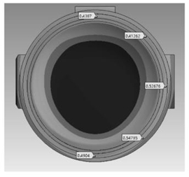
Figure 9 Deformation cloud picture of the wedge
4.4 Discussion on finite element analysis results
From the deformation cloud picture of the valve body, the deformation trend of the valve body's sealing surface is that the bottom deformation is the smallest, and the deformation gradually increases along the sealing surface. The maximum deformation on the sealing surface is 0.363 mm, and the minimum deformation is about 0.030 mm; the deformation in the middle is about 0.134 mm. The calculation results of the finite element conform to the actual working conditions of the valve body. When the deformation at the sealing surface of the valve body is greater than 0.001DN, the valve will leak due to excessive deformation of the valve body, because the maximum deformation of the valve body's sealing surface is less than 0.001 DN. Therefore, the valve body's structural design is reasonable.
By observing the deformation cloud picture of the wedge and analyzing the deformation of the valve body, it is found that the amount of deformation on the sealing surface of the wedge is greater than that of the valve body. The analysis results can verify that the slight deformation generated by the elastic groove of the wedge-shaped plate can compensate for the gap between the valve seat and the manufacturing deviation so that the sealing surface of the two sealing surfaces of the wedge and the valve seat can be completely matched.
5. Conclusion
The large-diameter wedge gate valve of DN1200 is selected as the research object in this article. Its structure and working principles are clarified, and the valve body of the wedge gate valve and main parts of the valve plate are designed, including the structure of the middle cavity in the valve body and distribution of reinforcing ribs, thicknesses of valve plates, elastic ratios as well as checking the strength and deformation of the valve body and wedge. The results show that the design in this article can fully meet the required strength.
