
Lift Metal Seated Plug Valves
The working principle, structural design, finite element analysis and manufacturing process of the main parts of the lift metal-seated plug valve are explained.
1. Overview
The plug valve has the characteristics of a simple structure and small flow resistance, but ordinary plug valves are sealed by direct contact between the plug and the valve body, which has disadvantages such as large opening and closing torque, easy wear of the sealing surface, and poor sealing performance. Ordinary sleeve plug valves, lubricating plug valves and general valves are not suitable for high temperatures. The lift metal-seated plug valve developed according to the working conditions solves the problem that the plug valve cannot be used for high temperatures.
2. Performance
The lift metal seated plug valve adopts the design of a pivot fixed integral plug, hard alloy seat and double roller guide groove, which realizes the function of lifting and rotating the valve without friction, and reduces the probability of abrasion, wear and bonding of the sealing surface during the operation of the valve. The lift metal seated plug valve has the advantages of novel structure, advanced technology, labor-saving operation, rapid opening and closing, good sealing, convenient maintenance, high-temperature purging and all-round installation, which is especially suitable for high-temperature steam pipelines and the pump outlet with high-pressure difference, and can also be used for occasions such as delayed coking systems, residual oil catalytic cracking units and ethylene cracking units.
3. Working principles
A lifting metal seated plug valve is mainly composed of bottom covers, lower support plates, valve bodies, plugs, upper support plates, bonnets, valve stems, brackets, cross pins, rollers, stem nuts, driving devices, etc. (Figure 1). The upper part of the valve stem is the trapezoidal thread, and the lower part of the valve stem is connected with the plug through a T-shaped groove. A horizontal pin is arranged in the middle part of the valve stem, and a roller is set at each end of the pin. The upper part of the bracket is provided with two guide grooves distributed at 180°, and the guide grooves include straight grooves and spiral grooves. When the valve is opened, the driving device such as a hand wheel drives the stem nut to rotate, the roller rolls along the straight groove; the stem and the plug rise together, and the plug and the sealing surface of the valve body are separated axially without friction. The stem nut continues to rotate. The roller rolls along the spiral groove; the stem and plug rotate 90° counterclockwise, and the valve is fully opened. When the valve is closed, the driving device drives the stem nut to rotate; the roller rolls along the spiral groove, and the stem and the plug rotate clockwise 90°; the stem nut continues to rotate, and the roller rolls along the straight groove. The stem and plug descend together. The plug and the sealing surfaces of the body come into contact until they are sealed.
4. Structural design
The valve design adopts API 599, and the sealing pair adopts a metal-seated structure, which is suitable for high temperatures. Because the sealing specific pressure of the lifting metal seated plug valve is controlled by the torque provided by the external actuator, it belongs to the forced sealing valve.

1. Bottom covers 2. Lower support plates 3. Valve bodies 4. Plugs 5. Upper support plates 6. Bonnets 7. Stems 8. Brackets 9. Cross pins 10. Rollers 11. Stem nuts 12. Handwheels
Figure 1 Lifting metal seated plug valves
4.1. Valve bodies
The end of the valve body is flanged, and the flow channel is Venturi ruled, that is, the cross-sectional area of the flow channel decreases gradually from the valve inlet and outlet to the sealing of the seat, but the size of the flow channel in the height direction increases slightly. The minimum wall thickness of the shell meets the requirements of avoiding permanent deformation and meeting the requirement of the stress concentration of non-circular channels under the load of the pressure test (1.5 times the maximum allowable working pressure).
According to actual inspections and tests, the parts where stress concentration has the greatest impact on the deformation of the valve body are in the cavity and sealing surface of the valve body, thus affecting the sealing of the valve. For the high-pressure valve body, integral casting ribs are provided on the outside (Figure 2 and Figure 3) or the wall thickness of the valve body is increased to ensure that the valve body has sufficient rigidity at high pressure. The sealing surface of the valve body is designed as an internal convex structure, which makes it more manufacturable and convenient for machining and grinding. When the valve is fully closed, the middle cavity is suitable for purging.

Figure 2 The distribution of static stress of the loading of the valve body
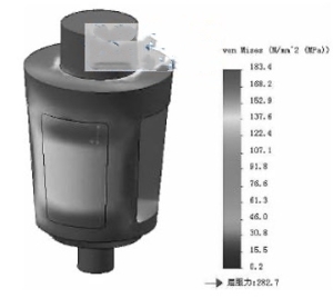
Figure 3 The distribution of static displacement of the valve body under loading
4.2. Plugs
The plug has an integral structure with good rigidity, which is conducive to the application of the valve under high-pressure differences. The through hole of the plug is designed to be approximately rectangular, and the plug is designed with upper and lower pivots to cooperate with the high-precision inner holes of the upper and lower support plates. The outer circle of the support plate is precisely matched with the inner hole at the end of the upper and lower flanges of the valve body, so that the medium pressure acting on the plug is transmitted to the valve body through the support plate, preventing the plug from vibrated due to scouring by high-speed fluid under high pressure and high-pressure difference and enhancing the stability of the plug. In addition, when the valve stem is required to be horizontal or inclined, this structure also eliminates the adverse effect of the plug on the performance of the valve due to its weight. Through analysis, the stress and deformation of the plug are concentrated in the middle of the plug and the edge of the through hole of the plug, which should be considered in the design (Figure 4 and Figure 5).
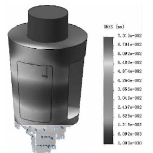
Figure 4 The distribution of static stress loading of plugs
Figure 5 The distribution of loading static displacement of plugs
The plug is generally made from cast carbon steel surfacing welding carbide. For pressure rating above Class 600, it is advisable to use forged carbon steel surfacing welding carbide, or use cast martensitic stainless steel heating surface hardening process; the hardness after heat treatment is controlled at 35 to 40HRC, and corrosion and bonding are prevented after grinding. The sealing surfaces of the valve body and the plug are all surfacing with hard alloy, which not only prevents seizure, but also prolongs the service life of the valve.
4.3. Valve stems
The structure of the valve stem refers to the design of the wedge gate valve stem. Considering that there is a horizontal pin hole in the middle of the valve stem, and the diameter of the valve stem is appropriately increased. Because the valve stroke is short, the screw part of the valve stem is only 1/10 to 1/5 of the gate valve of the same specification. Therefore, the opening speed of the metal seated plug valve is fast.
4.4. Bonnet and bottom covers
The sealing structure of the bonnet is designed as a concave-convex surface or a ring connection to meet the requirements of different pressure levels. For large-diameter valves, the split design of the bracket and bonnet is adopted. In addition, the valve stem hole of the metal seated plug valve bonnet is provided with an upper sealing seat, which cooperates with the 90° cone surface at the end of the valve stem to form the upper sealing pair of the valve, meets the requirements of online replacement of packing and is easy to maintain. There is a guide groove on the upper part of the valve bracket, and the guide groove cooperates with the roller to complete the two actions of lifting and rotating the plug. The flange at the upper end of the bracket is designed to install various actuators. The bottom cover is provided with discharge holes, which can be used to remove and purge the dirt in the body cavity.
5. Manufacture and inspection
The tapered sealing surface of the valve body and the plug of the lift metal-seated plug valve has a special structural shape and requires high machining accuracy, which is a key and difficult point in manufacturing. Firstly, a large CNC vertical lathe is used to process the tapered surface, and then a high-precision CNC grinding center is used to grind the sealing tapered surface of the valve body and the plug with the same grinding wheel, so that the surface roughness can reach Ra 0. 2μm. After testing the plug valve prototype several times in accordance with the requirements of API 598, the shell strength, high and low-pressure sealing and upper sealing tests were all qualified, and the prototype was successfully trial manufactured.
1. Overview
The plug valve has the characteristics of a simple structure and small flow resistance, but ordinary plug valves are sealed by direct contact between the plug and the valve body, which has disadvantages such as large opening and closing torque, easy wear of the sealing surface, and poor sealing performance. Ordinary sleeve plug valves, lubricating plug valves and general valves are not suitable for high temperatures. The lift metal-seated plug valve developed according to the working conditions solves the problem that the plug valve cannot be used for high temperatures.
2. Performance
The lift metal seated plug valve adopts the design of a pivot fixed integral plug, hard alloy seat and double roller guide groove, which realizes the function of lifting and rotating the valve without friction, and reduces the probability of abrasion, wear and bonding of the sealing surface during the operation of the valve. The lift metal seated plug valve has the advantages of novel structure, advanced technology, labor-saving operation, rapid opening and closing, good sealing, convenient maintenance, high-temperature purging and all-round installation, which is especially suitable for high-temperature steam pipelines and the pump outlet with high-pressure difference, and can also be used for occasions such as delayed coking systems, residual oil catalytic cracking units and ethylene cracking units.
3. Working principles
A lifting metal seated plug valve is mainly composed of bottom covers, lower support plates, valve bodies, plugs, upper support plates, bonnets, valve stems, brackets, cross pins, rollers, stem nuts, driving devices, etc. (Figure 1). The upper part of the valve stem is the trapezoidal thread, and the lower part of the valve stem is connected with the plug through a T-shaped groove. A horizontal pin is arranged in the middle part of the valve stem, and a roller is set at each end of the pin. The upper part of the bracket is provided with two guide grooves distributed at 180°, and the guide grooves include straight grooves and spiral grooves. When the valve is opened, the driving device such as a hand wheel drives the stem nut to rotate, the roller rolls along the straight groove; the stem and the plug rise together, and the plug and the sealing surface of the valve body are separated axially without friction. The stem nut continues to rotate. The roller rolls along the spiral groove; the stem and plug rotate 90° counterclockwise, and the valve is fully opened. When the valve is closed, the driving device drives the stem nut to rotate; the roller rolls along the spiral groove, and the stem and the plug rotate clockwise 90°; the stem nut continues to rotate, and the roller rolls along the straight groove. The stem and plug descend together. The plug and the sealing surfaces of the body come into contact until they are sealed.
4. Structural design
The valve design adopts API 599, and the sealing pair adopts a metal-seated structure, which is suitable for high temperatures. Because the sealing specific pressure of the lifting metal seated plug valve is controlled by the torque provided by the external actuator, it belongs to the forced sealing valve.
1. Bottom covers 2. Lower support plates 3. Valve bodies 4. Plugs 5. Upper support plates 6. Bonnets 7. Stems 8. Brackets 9. Cross pins 10. Rollers 11. Stem nuts 12. Handwheels
Figure 1 Lifting metal seated plug valves
4.1. Valve bodies
The end of the valve body is flanged, and the flow channel is Venturi ruled, that is, the cross-sectional area of the flow channel decreases gradually from the valve inlet and outlet to the sealing of the seat, but the size of the flow channel in the height direction increases slightly. The minimum wall thickness of the shell meets the requirements of avoiding permanent deformation and meeting the requirement of the stress concentration of non-circular channels under the load of the pressure test (1.5 times the maximum allowable working pressure).
According to actual inspections and tests, the parts where stress concentration has the greatest impact on the deformation of the valve body are in the cavity and sealing surface of the valve body, thus affecting the sealing of the valve. For the high-pressure valve body, integral casting ribs are provided on the outside (Figure 2 and Figure 3) or the wall thickness of the valve body is increased to ensure that the valve body has sufficient rigidity at high pressure. The sealing surface of the valve body is designed as an internal convex structure, which makes it more manufacturable and convenient for machining and grinding. When the valve is fully closed, the middle cavity is suitable for purging.
Figure 2 The distribution of static stress of the loading of the valve body
Figure 3 The distribution of static displacement of the valve body under loading
4.2. Plugs
The plug has an integral structure with good rigidity, which is conducive to the application of the valve under high-pressure differences. The through hole of the plug is designed to be approximately rectangular, and the plug is designed with upper and lower pivots to cooperate with the high-precision inner holes of the upper and lower support plates. The outer circle of the support plate is precisely matched with the inner hole at the end of the upper and lower flanges of the valve body, so that the medium pressure acting on the plug is transmitted to the valve body through the support plate, preventing the plug from vibrated due to scouring by high-speed fluid under high pressure and high-pressure difference and enhancing the stability of the plug. In addition, when the valve stem is required to be horizontal or inclined, this structure also eliminates the adverse effect of the plug on the performance of the valve due to its weight. Through analysis, the stress and deformation of the plug are concentrated in the middle of the plug and the edge of the through hole of the plug, which should be considered in the design (Figure 4 and Figure 5).
Figure 4 The distribution of static stress loading of plugs
Figure 5 The distribution of loading static displacement of plugs
The plug is generally made from cast carbon steel surfacing welding carbide. For pressure rating above Class 600, it is advisable to use forged carbon steel surfacing welding carbide, or use cast martensitic stainless steel heating surface hardening process; the hardness after heat treatment is controlled at 35 to 40HRC, and corrosion and bonding are prevented after grinding. The sealing surfaces of the valve body and the plug are all surfacing with hard alloy, which not only prevents seizure, but also prolongs the service life of the valve.
4.3. Valve stems
The structure of the valve stem refers to the design of the wedge gate valve stem. Considering that there is a horizontal pin hole in the middle of the valve stem, and the diameter of the valve stem is appropriately increased. Because the valve stroke is short, the screw part of the valve stem is only 1/10 to 1/5 of the gate valve of the same specification. Therefore, the opening speed of the metal seated plug valve is fast.
4.4. Bonnet and bottom covers
The sealing structure of the bonnet is designed as a concave-convex surface or a ring connection to meet the requirements of different pressure levels. For large-diameter valves, the split design of the bracket and bonnet is adopted. In addition, the valve stem hole of the metal seated plug valve bonnet is provided with an upper sealing seat, which cooperates with the 90° cone surface at the end of the valve stem to form the upper sealing pair of the valve, meets the requirements of online replacement of packing and is easy to maintain. There is a guide groove on the upper part of the valve bracket, and the guide groove cooperates with the roller to complete the two actions of lifting and rotating the plug. The flange at the upper end of the bracket is designed to install various actuators. The bottom cover is provided with discharge holes, which can be used to remove and purge the dirt in the body cavity.
5. Manufacture and inspection
The tapered sealing surface of the valve body and the plug of the lift metal-seated plug valve has a special structural shape and requires high machining accuracy, which is a key and difficult point in manufacturing. Firstly, a large CNC vertical lathe is used to process the tapered surface, and then a high-precision CNC grinding center is used to grind the sealing tapered surface of the valve body and the plug with the same grinding wheel, so that the surface roughness can reach Ra 0. 2μm. After testing the plug valve prototype several times in accordance with the requirements of API 598, the shell strength, high and low-pressure sealing and upper sealing tests were all qualified, and the prototype was successfully trial manufactured.
