
Analysis and Measures of Internal Leakages of Globe Valves (Part one)
The internal leakage in the use of globe valves is summarized and analyzed, and the measures to solve the problems are put forward.
A globe valve is an indispensable fluid control product in modern industry, and it is one of the most widely used valves at present. Its derivative products are very extensive, including various types of valves such as cut-off valves, regulating valves, throttling valves, needle valves and throttling cut-off and venting valves, which can not only cut off the medium quickly, but also regulate the medium in the pipeline. The following is an analysis of several common internal leakages in the application of globe valves, and measures to solve internal leakage are put forward.
The internal leakage of the vertical installation of the globe valve
1. Brief description of the internal leakage
The installation direction of the globe valve is generally divided into two types, one is horizontal installation, that is, the valve stem of the valve is in the vertical direction, and the channel axis of the valve is parallel to the horizontal plane. The other is the vertical installation direction, that is, the valve stem of the valve is parallel to the horizontal plane, and the axis of the valve passage is perpendicular to the horizontal plane. The installation direction of the valve is determined according to the design of the pipeline by the design institute, that is to say, horizontal installation and vertical installation are common installation methods and are inevitable. After the production and assembly of the globe valve are completed, the sealing test must be carried out, and the delivery can only be made after the test is passed. Usually, the sealing of the valve is good during the test, but when the valve is assembled to the vertical pipeline, there will be internal leakages.
2. Internal leakages of different sealing forms
Generally, the sealing surface of the globe valve is divided into two types: flat seals (Figure 1) and cone seals (Figure 2). According to the feedback in engineering applications, when the globe valve is installed vertically, the leakage mostly occurs in globe valves of the cone sealing, which usually leaks after the first use after installation, while the flat sealed globe valve is installed horizontally and vertically has almost the same service life.
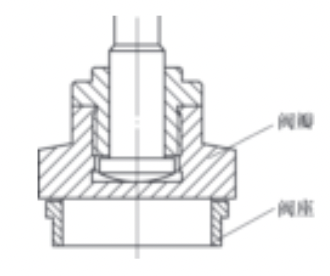
Figure 1 Plane-sealed globe valves
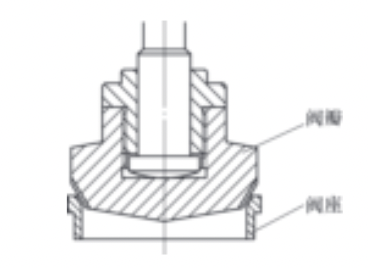
Figure 2 Cone-sealed globe valves
3. The analysis of the causes of internal leakages
From Figure 3, we can see the structural relationship of the internal parts of globe valves. The valve stem is often constrained by the packing and the upper sealing seat. The lower end of the valve stem is connected to the disc through clearance fit. The sealing surface of the lower end of the valve handle and the valve seat attach to form a seal. Figure 4 is a schematic diagram of the horizontal installation of the globe valve. When the valve stem pushes the valve disc to press against the valve seat, the sealing surface of the valve seat and the valve stem can have good contact. Figure 5 is a schematic diagram of the vertical installation of the globe valve. The axis of the sealing cone surface of the valve seat angularly deviates from the axis of the sealing cone surface of the valve seat. When the valve stem pushes the valve disc to press against the valve seat, the sealing surface cannot self-align and seal well, resulting in leakages.
It can be seen from the above that the inclination of the valve disc is the main factor leading to the internal leakage of the valve. There are two reasons for the excessive inclination of the valve disc. One is that there is an assembly gap between the valve disc and the valve stem. The second is that when the valve stem is placed horizontally, it becomes a cantilever beam. The valve disc produces a downward inclination due to the action of gravity. Deformation occurs for the valve stem due to the action of gravity, which further aggravates the inclination of the valve disc.
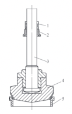
Figure 3 The sealing structure of globe valves
Packing 2. Upper sealing seats 3. Valve stems 4. Valve discs
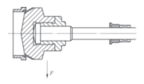
Figure 4 The schematic diagram of the horizontal installation of the globe valve

Figure 5 The schematic diagram of the vertical installation of globe valves
A globe valve is an indispensable fluid control product in modern industry, and it is one of the most widely used valves at present. Its derivative products are very extensive, including various types of valves such as cut-off valves, regulating valves, throttling valves, needle valves and throttling cut-off and venting valves, which can not only cut off the medium quickly, but also regulate the medium in the pipeline. The following is an analysis of several common internal leakages in the application of globe valves, and measures to solve internal leakage are put forward.
The internal leakage of the vertical installation of the globe valve
1. Brief description of the internal leakage
The installation direction of the globe valve is generally divided into two types, one is horizontal installation, that is, the valve stem of the valve is in the vertical direction, and the channel axis of the valve is parallel to the horizontal plane. The other is the vertical installation direction, that is, the valve stem of the valve is parallel to the horizontal plane, and the axis of the valve passage is perpendicular to the horizontal plane. The installation direction of the valve is determined according to the design of the pipeline by the design institute, that is to say, horizontal installation and vertical installation are common installation methods and are inevitable. After the production and assembly of the globe valve are completed, the sealing test must be carried out, and the delivery can only be made after the test is passed. Usually, the sealing of the valve is good during the test, but when the valve is assembled to the vertical pipeline, there will be internal leakages.
2. Internal leakages of different sealing forms
Generally, the sealing surface of the globe valve is divided into two types: flat seals (Figure 1) and cone seals (Figure 2). According to the feedback in engineering applications, when the globe valve is installed vertically, the leakage mostly occurs in globe valves of the cone sealing, which usually leaks after the first use after installation, while the flat sealed globe valve is installed horizontally and vertically has almost the same service life.
Figure 1 Plane-sealed globe valves
Figure 2 Cone-sealed globe valves
3. The analysis of the causes of internal leakages
From Figure 3, we can see the structural relationship of the internal parts of globe valves. The valve stem is often constrained by the packing and the upper sealing seat. The lower end of the valve stem is connected to the disc through clearance fit. The sealing surface of the lower end of the valve handle and the valve seat attach to form a seal. Figure 4 is a schematic diagram of the horizontal installation of the globe valve. When the valve stem pushes the valve disc to press against the valve seat, the sealing surface of the valve seat and the valve stem can have good contact. Figure 5 is a schematic diagram of the vertical installation of the globe valve. The axis of the sealing cone surface of the valve seat angularly deviates from the axis of the sealing cone surface of the valve seat. When the valve stem pushes the valve disc to press against the valve seat, the sealing surface cannot self-align and seal well, resulting in leakages.
It can be seen from the above that the inclination of the valve disc is the main factor leading to the internal leakage of the valve. There are two reasons for the excessive inclination of the valve disc. One is that there is an assembly gap between the valve disc and the valve stem. The second is that when the valve stem is placed horizontally, it becomes a cantilever beam. The valve disc produces a downward inclination due to the action of gravity. Deformation occurs for the valve stem due to the action of gravity, which further aggravates the inclination of the valve disc.
Figure 3 The sealing structure of globe valves
Packing 2. Upper sealing seats 3. Valve stems 4. Valve discs
Figure 4 The schematic diagram of the horizontal installation of the globe valve
Figure 5 The schematic diagram of the vertical installation of globe valves
