Abstract: This paper presents the key parameters and technical challenges in the development of an NPS24 Class 900 high-pressure, large-diameter, bidirectional-sealing, program-controlled rising-stem ball valve. To overcome the limitations of conventional designs—such as insufficient bidirectional sealing, stem scoring, and challenging seat maintenance—structural optimizations were implemented. Strength analyses of the valve body and bonnet, performed using ASME B16.34 guidelines and finite element methods, confirmed their structural safety. Calculations of the torsional angle and stiffness at the stem spiral groove confirmed that the stem possesses sufficient strength, while process optimizations in LC1 casting substantially improved low-temperature impact toughness, meeting the requirement of ≥27 J at –52 °C. Optimized stem machining ensured durability for up to 750 cycles per year, while the ball sealing surface, created using a flame-spraying fusion process, formed a metallurgical bond with the substrate, enhancing wear and erosion resistance. Bidirectional high-pressure liquid, high-pressure gas, and low-pressure gas sealing tests all met GOST 9544 Class A standards, and the valve operated smoothly under both no-load and maximum differential pressure, with no sticking, stalling, or vibration. Comprehensive testing confirms the successful domestic development of the valve. Rising-stem ball valves (also called orbit ball valves) combine the advantages of ball, gate, globe, and plug valves, featuring wear-free operation and positive sealing. Program-controlled rising-stem ball valves are pneumatically actuated and integrated with DCS or PLC systems for remote computer control. With demonstrated reliability under frequent operation and temperature fluctuations, these valves are widely used in molecular sieve units, isomerization, propane dehydrogenation, natural gas dehydration, and purification processes. This study focuses on the development and application of these valves in a molecular sieve unit at a natural gas processing plant in Russia.
Valve Specifications: NPS 24
Pressure Rating: Class 900
Application Location: Natural gas dryer outlet
Process Medium: Dry natural gas
Medium State: Gas/steam
Maximum Shutoff Differential Pressure: 8.34 MPa
Design Temperature: –52 °C to 350 °C
Construction: Full-bore, top-entry, hardware seal
Body and Bonnet Material: ASTM A352-2021 LC1
Seat Material: ASTM A182-2023 Japan F316 + Ni60
Ball Material: ASTM A351-2018 Japan CF8M + Ni65
Stem Material: ASTM A564-2019a 630
Packing Material: Low-leakage graphite composite packing
Seat Class: Bidirectional, GOST 9544-2015 Class A
End Connection: ASME B16. May 2020, RTJ
Actuator: Pneumatic (with buffer oil tank), double-acting
Air Source Failure Position: Hold-in-place
Maximum Opening/Closing Time: ≤150 seconds
The key challenges in developing this NPS 24 Class 900 high-pressure, large-diameter, bidirectional-sealing, program-controlled rising-stem ball valve are:
· The valve must achieve bidirectional zero-leakage performance.
· It must operate reliably across a wide temperature range of –52 °C to 350 °C.
· t must meet a high-frequency actuation requirement of 750 cycles per year.
· The valve stem machining and spray coating must satisfy strict requirements for the high-pressure, large-diameter ball sealing surface.
· Both the valve body and pneumatic actuator must maintain integrity at low temperatures down to –52 °C.
During development, the valve structure was optimized to resolve key issues found in conventional rising-stem ball valves, including inadequate bidirectional sealing, lower support shaft strain, and difficulties in seat maintenance. The structure of the high-pressure, large-diameter, bidirectional-sealing, program-controlled rising-stem ball valve is illustrated in Figure 1.
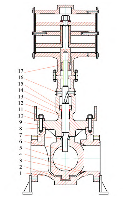
Figure 1. Structural schematic of the high-pressure, large-diameter, bidirectional-sealing, programmable rising-stem ball valve
1. Valve body 2. Bushing 3. Seat retainer 4. Valve seat 5. Ball 6. Stem 7. Roller 8. Gasket 9. Bonnet 10. Stud
11. Nut 12. Low-leakage composite packing 13. Spacer ring 14. Packing gland 15. Packing flange 16. Guide pin 17. Pneumatic actuator assembly
(1) Hardened Contact Area Between Valve Cover and Stem
As shown in Figure 2, the contact surface at the lower end of the valve cover and the valve stem is hardened with Stellite carbide, replacing the conventional upper sleeve found in traditional rising-stem ball valves. This treatment significantly improves wear resistance and ensures reliable operation for up to 750 cycles per year.
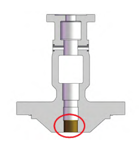
Figure 2. Hardened contact area between the valve cover and stem
(2) Cast ball with integrated lower support shaft
As shown in Figure 3, the lower support shaft is cast integrally with the ball, providing high strength, smooth operation, and reduced torque. In addition to the nickel-based alloy coating on the ball sealing surface, the lower support shaft is hardened with Stellite carbide, enhancing wear resistance and preventing shaft strain.
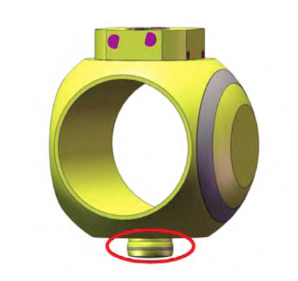
Figure 3. Integrated lower support shaft design
(3) Floating seat design
As shown in Figure 4, the valve features a floating seat design. During reverse sealing, the medium pressure acts on the sub-seat, slightly pressing it against the ball surface. This ensures tight contact between the seat and ball. As the medium pressure increases, the contact stress between the sealing surfaces rises, achieving effective bidirectional sealing.
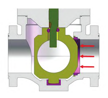
Figure 4. Floating seat design
(4) Online seat replacement design
The valve seat can be replaced online without requiring any special tools, allowing for quick maintenance and reduced downtime. By loosening the seat retaining ring and disengaging it from the body threads, the seat can be quickly removed and replaced, minimizing maintenance costs and downtime.
(5) Pneumatic actuator with buffer tank
The pneumatic actuator, equipped with a buffer tank, slows the piston’s opening speed, eliminates noise, and ensures smooth valve operation. This design minimizes stem strain and deformation while meeting the high-frequency actuation requirement of 750 cycles per year.
The valve body and bonnet, as the primary pressure-bearing components of this NPS 24 Class 900 high-pressure, large-diameter, bidirectional, programmable rising-stem ball valve, are critical to its structural integrity. The valve body has a complex three-way structure, while the bonnet features an extended T-shaped configuration. Both components are prone to stress concentration. To ensure the pressure boundary’s integrity, the strength of the valve body and bonnet was assessed per ASME B16.34-2020 and verified using finite element analysis (FEA).
The wall thickness of the valve body and bonnet was calculated using the ASME B16.34-2020 method:
t=0.10449d+2.54=62.1 mm
Here, df is taken as 570 mm in accordance with API 6D-2021. Considering additional pipeline loads and operational forces, the actual minimum wall thicknesses are set to 75 mm for the valve body and 69 mm for the bonnet.
The valve body strength was analyzed using the finite element method (FEM) in accordance with ASME BPVC VIII-2:2023.
Meshing
The mesh was generated using adaptive and local refinement techniques, resulting in 721,895 nodes and 486,666 elements, as shown in Figure 5.
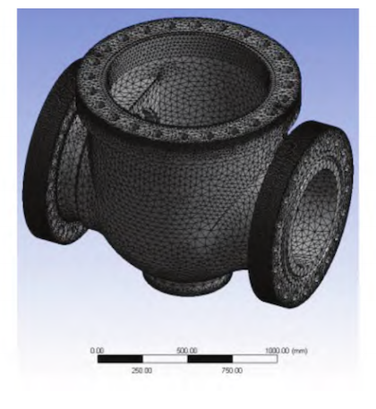
Figure 5: Valve body meshing
Load Application
In addition to internal pressure, the following loads were applied:
Bolt forces applied to the flanges near the center plane.
Sealing force exerted by the annular gasket on the two inclined surfaces.
Bolt forces applied to the center flange at the bonnet connection.
According to API 6D-2021, Section 5.1 (“Design Criteria and Calculations”), if the chosen design specification or standard specifies a test pressure less than 1.5 times the maximum allowable working pressure, the calculation pressure must be increased to account for hydrostatic testing. Accordingly, the pressure amplification factor used in the FEM analysis was:

Loads and Constraints
As shown in Figure 6, the applied loads and constraints were:
Internal pressure: 17.29 MPa
Bolt force per bolt near the center-plane flange: 818,393 N
Sealing force from the annular gasket: 16,367,860 N
Bolt force per bolt on the bonnet connection center flange: 860,987 N
The valve body’s center of gravity was fixed with boundary constraints.
Stress and Deformation Analysis
The equivalent stress distribution is shown in Figure 7. The maximum stress of 657.35 MPa occurs at the junction of the valve seat bore top plane and the internal cavity, a typical structural discontinuity. The equivalent deformation distribution is shown in Figure 8, with a maximum deformation of 1.3559 mm located on the symmetrical arc surface near the front and rear of the center flange.
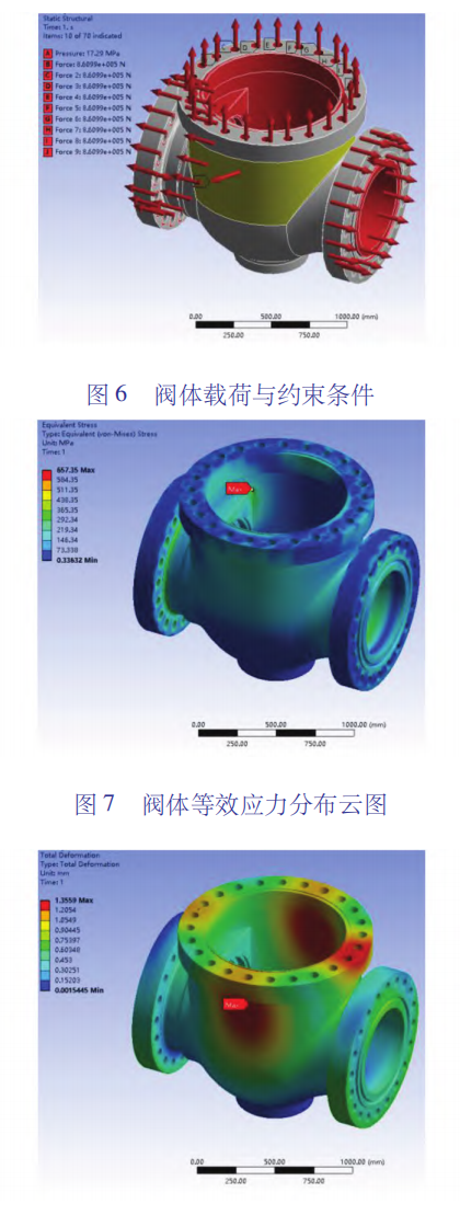
Figure 6: Valve Body Loads and Constraints
Figure 7: Equivalent Stress Distribution of the Valve Body
Figure 8: Equivalent Deformation Distribution of the Valve Body
The maximum stress exceeded the allowable 160 MPa specified for the valve body material in ASTM A352-2021 ICI. Therefore, stress linearization was performed in accordance with ASME BPVC VIII-2, as shown in Figure 9.
Assessment Item 1: Primary local membrane stress P=158.99 MPa<1.5S=240.0 MPa Result: Qualified.
Assessment Item 2: P+Pb+Q=313.01 MPa<3S=480.0 MPa Result: Qualified.
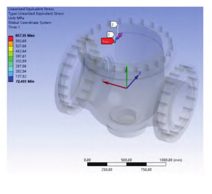
Figure 9: Stress Linearization at the Maximum Stress Point on the Valve Body
The bonnet strength was evaluated using finite element analysis (FEA) following ASME BPVC VIII-2:2023.
Meshing
Adaptive and local refinement techniques were used to generate the mesh, resulting in 242,203 nodes and 84,409 elements, as shown in Figure 10.
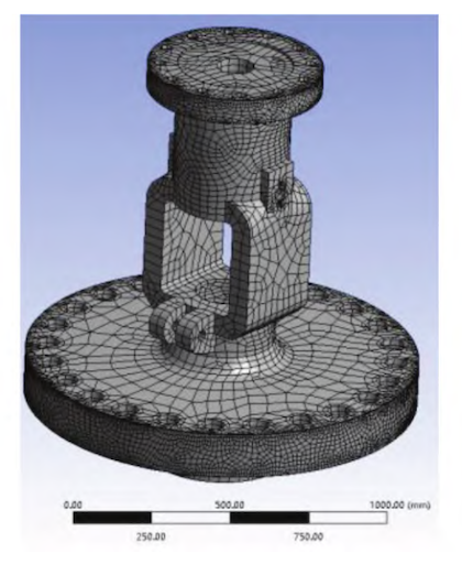
Figure 10: Bonnet Meshing
Loads and Constraints
In addition to internal pressure, the following loads were applied to the bonnet: bolt forces on the upper surface of the lower flange connecting to the valve body, and bolt forces on the lower surface of the upper flange connecting to the pneumatic actuator.
Loads and Constraints
As shown in Figure 11, the valve body is subjected to an internal pressure of 17.29 MPa in the bonnet cavity. A force of 860,987 N is applied to each bolt on the lower flange connecting to the valve body, and 84,594 N is applied to each bolt on the upper flange connecting to the pneumatic actuator. The bonnet’s center of gravity is fixed to provide a boundary constraint.
Figure 12 shows the bonnet’s equivalent stress distribution. The maximum stress occurs at the edge of the center flange hole, a typical location for structural discontinuities.
The maximum stress in the bonnet is 281.26 MPa. Figure 13 shows the equivalent deformation distribution, with a maximum deformation of 0.79396 mm at the outer diameter of the flange connecting to the pneumatic actuator.
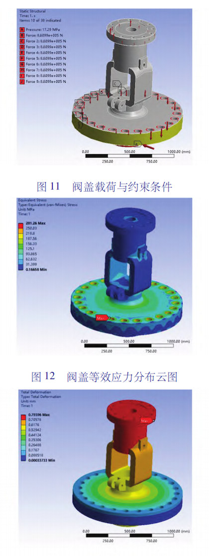
Figure 11: Bonnet Loads and Constraints
Figure 12: Bonnet Equivalent Stress Distribution
Figure 13: Bonnet Equivalent Deformation Distribution
The maximum stress in the bonnet exceeds the allowable stress of 160 MPa for the material, as specified in ASTM A352 2021 IC1. Therefore, stress linearization is required prior to the strength assessment, as shown in Figure 14. This assessment is carried out in accordance with ASME BPVC Section VIII, Division 2 (2023).
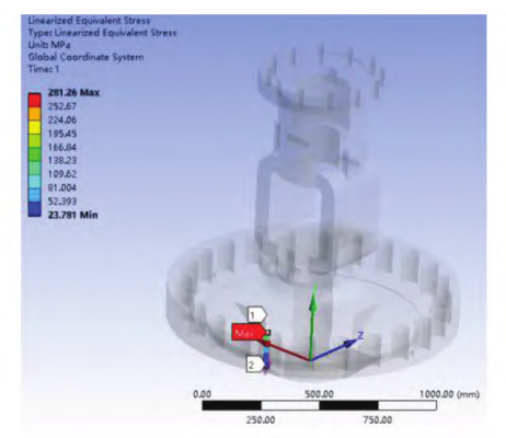
Figure 14: Linearized Equivalent Stress Contour at the Maximum Stress Point on the Bonnet
Assessment Item 3: The primary local membrane stress (Pm) must be less than 1.5 Sm.
Calculation: Pm = 73.544 MPa; 1.5 Sm = 240.0 MPa.
Result: Requirement met.
Assessment Item 4: The combined primary membrane stress (Pm), primary bending stress (Pb), and secondary bending stress (Q) must be less than 3 Sm.
Calculation: Pm + Pb + Q = 169.01 MPa; 3 Sm = 480.0 MPa.
Result: Requirement met.
The strength calculations and analyses confirm that both the valve body and bonnet are structurally sound, ensuring the integrity of the pressure boundary between them.
The valve stem, a critical component of the NPS 24 Class 900 high-pressure, large-diameter, bidirectional-sealing, program-controlled rising-stem ball valve, is susceptible to stress concentration and damage at the spiral groove, making it the most vulnerable part of the stem. During valve operation, torque is transmitted to the stem, causing deformation at the spiral groove. Therefore, calculating the torsion angle and torsional stiffness at this location is essential to verify the stem’s structural integrity.
The torsion angle of the stem spiral groove relative to the top of the stem was calculated to be 0.093°.
The torsional stiffness at the stem spiral groove was calculated as 0.098°/m.
Torsion Angle Evaluation
Evaluation Criterion: θ ≤ ω
According to the Appendix of MSS SP-134-2012-10, “Low-Temperature Valves with Extended Body and Bonnet” (Section XI.1.6), the allowable torsion angle is 2°.
The calculated torsion angle at the bottom of the stem spiral groove relative to the top of the stem is well below the allowable limit, confirming that the torsion angle requirement is fully satisfied.
Torsional Stiffness Evaluation
Evaluation Criterion: θ ≤ β
According to Mechanics of Materials, the allowable torsional stiffness for shafts used in precision machinery is 0.25–0.5°/m.
The calculation indicates that the torsional stiffness of the stem spiral groove lies within the allowable range, confirming that the torsional stiffness requirement is met.
To ensure reliable operation at ambient temperatures as low as –52 °C, the valve body and pneumatic actuator were made from ASTM A352-2021 LC1 steel. According to the standard, the average Charpy V-notch impact strength of LC1 castings at –59 °C must exceed 18 J, and no individual specimen may be below 14 J. However, to ensure safe operation in Russia’s high-altitude cold regions—where brittle fracture could lead to catastrophic valve failure—the customer required a minimum impact energy of 27 J at –52 °C. This requirement far exceeds the ASTM A352 standard, making it essential to optimize the LC1 casting process.
EAF + LF Melting
Using an Electric Arc Furnace (EAF) combined with a Ladle Refining Furnace (LF) enhances steel purity by minimizing the number and size of inclusions, thereby significantly improving impact toughness, particularly at low temperatures.
Alloy Composition Control
In addition to carefully controlling carbon, manganese, phosphorus, sulfur, and molybdenum, the nickel content should be maintained between 0.30% and 0.40% by mass. This composition optimizes the strengthening effect of nickel while enhancing the steel’s plasticity and toughness, especially its low-temperature impact resistance.
Heat Treatment Optimization
Quenching and tempering provide significantly higher low-temperature impact toughness than normalizing and tempering, making this the preferred heat treatment method.
Impact Testing
Each heat of castings must undergo low-temperature impact testing, and the results at –52 °C must meet the special requirement of ≥27 J.
Chemical and Mechanical Testing
The chemical composition and mechanical properties of each batch, produced under the same heat and heat treatment conditions, must be verified to fully comply with ASTM A352-2021.
Radiographic Inspection
All castings undergo radiographic testing, and the results must comply with ASME B16.34-2020.
Visual Inspection
All castings are visually inspected to ensure compliance with MSS SP-55-2011, Grade 4B.
Result:
After optimizing the casting process, the LC1 castings’ low-temperature impact toughness was significantly improved, consistently achieving ≥27 J at –52 °C, fully satisfying the customer’s enhanced requirements.
Conventional machining of rising-stem ball valve stems often cannot meet the required tolerances and surface roughness for the track groove, wedge surface, and bottom left and right flat surfaces. While these stems may be adequate for manual or electrically actuated rising-stem ball valves, high-pressure, large-diameter, program-controlled rising-stem ball valves experience significant wear in these regions. This can lead to valve seizure and failure to actuate. Moreover, stems manufactured using conventional methods are not hardened; after repeated use, the outer cylindrical surface, wedge surface, front and rear flat surfaces, and bottom left and right flat surfaces often exhibit strain and seizure, further impairing valve performance.
To meet the high-frequency actuation requirement of 750 cycles per year, the valve stem machining process was optimized. Key improvements include:
Simultaneous Track Groove Milling
A four-axis drilling and milling center machines the track grooves simultaneously at a 0° stem orientation, ensuring precise symmetry between the two grooves.
Precision Machining Relative to the Track Groove
Low-speed wire EDM is used, with the track groove serving as the reference, to machine the wedge surface and the bottom left and right planes. This ensures accurate positional tolerances and the required surface finish for these critical areas.
Hardening Treatment
The stem’s outer diameter, lower conical surface, wedge surface, lower end face, front and rear planes, and bottom left and right planes are all hardened to prevent strain, seizure, and premature wear.
The high-pressure, large-diameter ball sealing surface is coated using a flame-spray fusion process, forming a metallurgical bond between the coating and the substrate. A specialized KIIOY formula is applied, producing a coating thickness of ≥1.0 mm with a hardness of 63–65 HRC. This process significantly enhances the wear and erosion resistance of the valve under high-pressure, large-diameter operating conditions.
Valve performance testing includes shell testing, bidirectional high-pressure liquid and gas sealing, bidirectional low-pressure gas sealing, no-load actuation, and actuation under maximum differential closing pressure. Shell and sealing tests were conducted in strict accordance with GOST 9544-2015 and GOST 33257-2015 standards. The bidirectional high-pressure liquid, high-pressure gas, and low-pressure gas sealing tests all satisfied the Class A requirements of GOST 9544-2015. During both no-load and maximum differential pressure actuation tests, the valve operated smoothly, without sticking, creeping, or vibration. It opened within 117–120 seconds and closed within 88–90 seconds, meeting the maximum opening/closing time requirement of ≤150 seconds.
This article has presented the key design parameters and development challenges of an NPS 24 Class 900 high-pressure, large-diameter, bidirectionally sealed, programmable rising-stem ball valve. The main conclusions are summarized as follows:
(1) The conventional rising-stem ball valve design was successfully optimized to address critical issues including bidirectional sealing failure, insufficient support shaft rigidity, and difficult seat maintenance.
(2) Key structural improvements included: surface hardening of the bonnet-stem contact area, implementation of a one-piece cast ball with integrated support shaft, and adoption of a floating seat design with online replacement capability.
(3) The actuation system was enhanced through incorporation of a pneumatic actuator with buffer tank, ensuring reliable operation and programmability.
(4) Pressure boundary integrity was verified through finite element analysis and ASME B16.34-2020 compliance calculations, confirming the structural adequacy of valve body and bonnet components.
(5) Stem strength and torsional stiffness were validated through specialized calculations of the spiral groove geometry, demonstrating suitability for maximum operating torque requirements.
(6) Material performance was significantly improved through optimization of LC1 casting process, achieving enhanced low-temperature impact toughness exceeding the required ≥27 J at -52 °C.
(7) The integrated design approach successfully resolved the technical challenges of bidirectional sealing, structural integrity, and maintenance accessibility while maintaining full pressure containment capability.
(8) The developed valve meets all specified performance requirements for high-pressure applications and represents a significant advancement in large-diameter, high-pressure ball valve technology.
These comprehensive improvements ensure reliable operation under extreme conditions while providing enhanced safety margins and maintenance flexibility compared to conventional designs.