 Pneumatic Membrane Control Valve
Attentive people will find that there is a device hanging under the head of each control valve. Those familiar with it must know that this is the heart of the control valve. The valve positioner can adjust the amount of air into the valve head (pneumatic membrane), so that the position of the valve can be accurately controlled.
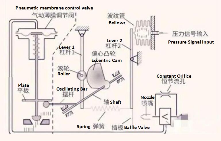
The valve positioner include intelligent positioner and mechanical positioner. Today we discuss the latter one, which are shown in the picture.
Working Principle of Mechanical Pneumatic Valve Positioner:

In the figure, the components of the mechanical pneumatic valve positioner are basically explained one by one. The next step is to see how it works.
The air source comes from the compressed air of the air compressor station. There is also an air filter pressure regulator in front of the air source inlet of the valve positioner for purifying the compressed air. The gas source from the outlet of the pressure reducing valve enters from the valve positioner, and the amount of air entering the membrane head of the valve is determined by the output signal of the controller.
The electrical signal output by the controller is 4 - 20mA, and the pneumatic signal is 20Kpa-100Kpa. From electrical signal to pneumatic signal, the process is conducted through an electrical converter.
When the electrical signal, output by the controller, is converted into a corresponding gas signal, the converted gas signal then impact the bellows. The lever 2 moves around the fulcrum, and the lower section of it moves to the right near the nozzle. The back pressure of the nozzle increases, and after being amplified by the pneumatic amplifier (the part with smaller symbol in the figure), a part of the air source is sent to the air chamber of the pneumatic membrane, making the valve stem with the valve core move downward, to reduce the valve’s opening automatically and gradually. At this time, the feedback rod (swing rod in the figure), connected with the valve stem moves downward around the fulcrum, leading the front end of the shaft to move downward, too. As a result, the eccentric cam connected with it rotates counterclockwise while the roller rotates clockwise and moves leftward, thus stretching the feedback spring. Since the lower section of lever 2, pulled by the feedback spring, moves to the left, it will reach force balance with the signal pressure functioning on the bellows, thus the valve is fixed at a certain position to stop operate.
Through the introduction of the above, we now have a certain understanding of the mechanical valve positioner, and it is better to disassemble it manually when there is an opportunity to operate it, so as to deepen the position and name of each part of the positioner. Therefore, the discussion on mechanical valves comes to an end, and in the next moment, knowledge will be expanded for you to get a deeper understanding of the control valves.
