The valve assembly of a control valve consists of the valve internals and the valve body. The control valve internals include the valve plug, valve stem, packing box, and upper valve bonnet. Among these components, the packing box is responsible for sealing the valve stem, employing an elastic method to prevent process medium leakage along the valve stem's surface due to reciprocating or rotating motion. It is an integral part of the valve body, and valve stem sealing is primarily achieved through the packing box.
Valve packing serves as the dynamic sealing filling material, typically installed within the packing box of the upper valve bonnet. Its purpose is to prevent leakage caused by the movement of the valve stem in response to the controlled medium. Commonly used packing materials are mainly categorized into two types based on material: polytetrafluoroethylene (PTFE) and expanded graphite.

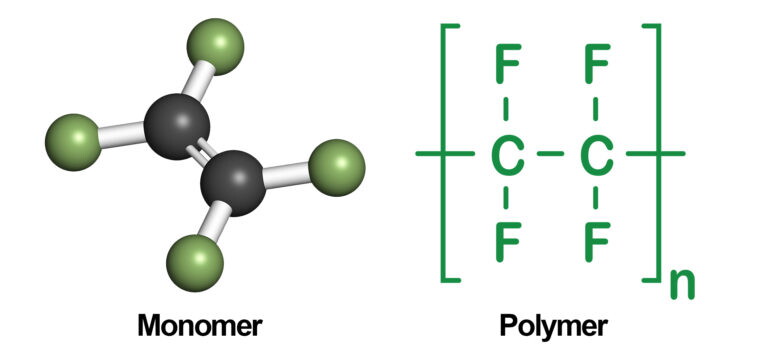
Polytetrafluoroethylene (PTFE) is a high polymer compound formed by the polymerization of tetrafluoroethylene. It possesses excellent chemical stability, corrosion resistance, sealing properties, high lubrication, non-adhesiveness, electrical insulation, and good aging resistance. Its corrosion resistance even surpasses that of glass and ceramics, exhibiting excellent resistance to strong acids, strong alkalis, and strong oxidants, making it an ideal sealing material. However, its temperature resistance is poor; PTFE begins to undergo extremely slight degradation above 200°C, experiencing creep under pressure or heat, thereby affecting sealing performance. Additionally, it is unsuitable for use in molten alkaline solutions or fluoride environments.
This material is manufactured by pressing polytetrafluoroethylene bulk into a braided form. It is an open material with good flexibility, durability, excellent sealing effect, and convenient replacement, making it the most widely used material.
Generally machined from polytetrafluoroethylene rod material, this packing structure is V-shaped. When compressed at both ends, due to the small friction coefficient of PTFE, it provides lubrication and excellent sealing performance. The characteristics of V-shaped packing rings include: under the pressure of the medium inside the valve, the lip edge of the outer ring always remains tightly attached to the inner wall of the packing box, ensuring static sealing. Similarly, under pressure, the lip edge of the inner ring always remains tightly attached to the valve stem to ensure dynamic sealing, even if the valve stem moves up and down.
By adding glass fibers, graphite, and molybdenum disulfide, the performance of PTFE can be enhanced to improve its resistance to creep and thermal conductivity. However, this increases hardness and decreases corrosion resistance and sealing performance.

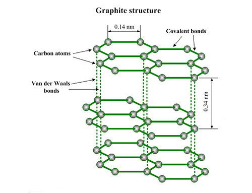
Expanded graphite material belongs to non-fibrous materials, obtained by removing impurities from natural flake graphite. After treatment with strong oxidizing mixed acids, it becomes oxidized graphite. Upon heating, oxidized graphite decomposes, releasing carbon dioxide, resulting in a significant volume expansion and transforming into expanded graphite, which is porous, soft, and resilient. It is a material known for its long lifespan and excellent sealing performance.
Expanded graphite exhibits minimal changes in its physical properties from ultra-low temperatures of -250°C to high temperatures of +600°C.
Apart from corrosion in strong oxidizing media like nitric acid and concentrated sulfuric acid, expanded graphite is almost immune to corrosion in other acids, alkalis, and solvents.
Similar to natural graphite, expanded graphite easily generates sliding under external force, thus possessing self-lubricating properties and ensuring good sealing performance.
Due to its porous and resilient nature, expanded graphite has good rebound resilience. When the shaft or shaft sleeve exhibits radial runout due to manufacturing or installation eccentricity, expanded graphite demonstrates sufficient floating performance. Even if cracks occur, it still maintains tight contact, ensuring tight sealing and preventing leakage.
(1) Filament or braided: This type of packing has good elasticity and can wrap around the valve stem while purifying its surface. Braided graphite packing can overcome leakage caused by wear in other types of graphite packing, but its braided structure creates gaps, making it prone to seepage.
(2) Sheet graphite: Made by compressing several graphite sheets into packing rings, its texture is perpendicular to the valve stem surface, forming a square cross-section, making fluid penetration difficult. However, it also reduces the ratio of axial pressure to radial pressure, requiring greater compression force for sealing.
(3) Bent sheet graphite: Its texture is parallel to the axial direction of the valve stem, processed from several graphite sheets. The pressure during compression is much higher than during operation, preventing further contraction in the packing box. It is prone to seepage at high temperatures due to its principle. However, due to easy processing and low cost, it is widely used.
In practical use, control valves may experience packing leakage due to various factors. Site maintenance should involve specific analysis and judgment based on the actual usage conditions of the valve to eliminate leakage causes fundamentally and address safety hazards. The main reasons for leakage can be summarized as follows:
(1) Improper selection of packing material or type: For instance, using PTFE packing in conditions ranging from 150°C to 200°C may lead to slight creep over extended periods under critical conditions, resulting in decreased sealing performance due to high-pressure medium effects. Similarly, selecting braided packing for highly permeable media such as liquid ammonia, tar, or fuel can lead to leakage under high-temperature and high-pressure conditions.
(2) Improper packing installation methods: After packing is installed into the packing box and subjected to axial pressure from the gland, plasticity of the packing generates radial force, causing it to make contact with the valve stem tightly. If the packing is tightened unevenly during installation, leading to uneven force distribution, some parts of the packing may not make proper contact or even lose contact, resulting in packing leakage.
(3) Relative motion between the valve stem and packing during valve operation, known as axial movement. During operation, the packing box of control valves is a common area for leakage, especially under the influence of high temperature, high pressure, and highly permeable fluid media. The main cause of packing leakage is interface leakage. For textile packing, there may also be leakage (pressure medium leaking out along the tiny gaps between packing fibers). Interface leakage between the valve stem and packing is caused by gradually diminishing contact pressure, aging, and loss of elasticity of the packing. Under these conditions, pressure medium may leak out along the contact gap between the packing and valve stem.
(4) Frequent valve actuation, valve stem bending, wear, corrosion, and decreased smoothness lead to packing wear and leakage.
(5) Changes in valve operating conditions, such as during the heating process when the device is started up, cause significant changes in the hot medium as the valve moves from cold to hot conditions. Thermal expansion of the valve stem due to heating may increase the packing clearance, resulting in severe packing leakage.
(6) Loose or skewed packing glands or horizontal installation of control valves, may result in poor contact between the valve stem and packing, leading to excessive or insufficient clearance.
(1) To facilitate packing insertion, chamfer the top end of the packing box and place a corrosion-resistant metal protection ring with appropriate clearance at the bottom of the packing box (the contact surface with the packing should not be sloped) to prevent the packing from being pushed out by medium pressure.
(2) Improve the surface accuracy and smoothness of the valve stem and packing box. If the sum of the friction coefficients between various movable parts is zero, the force acting on the packing gland will be evenly distributed to the entire packing without any attenuation. Although the actual sum of friction forces cannot be zero and will decrease with the distance from the gland, the friction force, the radial force acting on the packing will decrease. The greater the friction, the greater the pressure attenuation. Once the sealed pressure exceeds the force acting on the packing, leakage begins. Therefore, during maintenance, the valve stem and packing box should be free from scratches, pitting, and wear, with good smoothness.
(3) Select suitable materials with resistance to temperature changes, creep resistance, relaxation resistance, and oxidation resistance. Generally, PTFE is preferred when conditions allow, while graphite is chosen when PTFE is not suitable. Hybrid packing can also be used: mixing graphite and PTFE, or using O-rings with V-shaped packing. Graphite packing can be used for media with strong permeability.
(4) When filling the packing, add it coil by coil and use a pressing tool to press each coil tightly to ensure uniform force distribution. Open packing should be placed with gaps staggered at 90° or 120°, and the number of packing coils should be appropriate to prevent external leakage. Insufficient packing may cause leakage as the packing gland enters the packing box.
(5). For PTFE packing affected by spring force, the gland screws should be symmetrically tightened without deviation. Other types of packing do not need to be tightened too much, just enough to prevent leakage.
(6) After a new valve or a control valve that has just been overhauled is put into operation, check for any leakage in the packing. If leakage is found, deal with it promptly to prevent the leakage from getting worse.
(1) When cutting molded packing, use a 45° angle cut, and during installation, ensure that the cuts of each coil are staggered by 90° or 120°.
(2) When using molded PTFE packing under high pressure, pay attention to its cold flow characteristics.
(3) Using flexible graphite rings alone may result in poor sealing effectiveness; they should be combined with graphite braided packing.
(4) Graphite packing should not be used with strong oxidizing agents such as concentrated sulfuric acid or nitric acid.
(5) The dimensional accuracy and surface roughness of the packing box, as well as the dimensional accuracy and surface roughness of the valve stem, are critical factors affecting the sealing effectiveness of molded packing.
