Ball valves used in the electric power industry play a vital role in controlling the flow, opening and closing of the medium in the pipeline, and can realize flowing and cutting off of the medium. During the movement of the mechanism, the ball valve and the valve seat are sealed and rotated for a long time, resulting in long-term, high-frequency sliding friction between the two, and phenomena such as thinning, wear, and deformation occur, which seriously affect the ball valve's regulation and control of the medium. The surface modification of the hard coating on the outer surface of the ball valve and the inner surface of the valve seat is very important. The flame spraying maximizes the hardness and wear resistance of the surface through mechanical bonding. The ball valve and the valve stem's rotating hinge in a thermal power plant were deformed and the coating fell. The base material of the ball valve was 12Cr1MoV low alloy steel. The diameter of the ball valve is 43mm; the diameter of the circular hole is 22mm, and the size of the rectangular hinge is 25 mm × 17 mm. The flame spray coating is made from NiCr-CrsC2. A series of physical and chemical inspections are performed to analyze the reasons for the peeling of coatings to prevent such accidents from happening again.
1. Physical and chemical inspection
1.1 Macroscopic observation
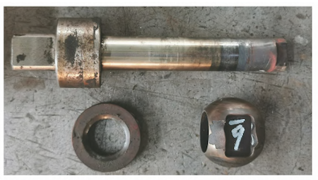
The valve stem is linked with the ball valve through a rectangular hinge, driving the ball valve to rotate on the annular valve pad. High-frequency, long-term articulation and rotation caused significant deformation at the contact points between the valve stem and the ball valve. The rectangular end of the valve stem was severely worn, and serious extrusion pits happened inside the rectangular groove of the ball valve. At the same time, the hard coating covering the surface of the ball valve at the hinge cracked and fell. The macroscopic morphology of the ball valve, valve stem and valve gasket with the coating peeled off is shown in Figure 1. It can be seen from Figure 1 that the surface coating of the ball valve is severely cracked, and the cracked area is mainly concentrated near the long side of the rectangular groove. The inside of the groove and the hinge of the valve stem are severely deformed. The broken coating has sharp corners and a brittle cracking morphology. At the same time, since there is no coating that is broken due to deformation in the rectangular groove, it can be confirmed that flame spraying should be performed first and the machining of the rectangular groove when processing the ball valve.

Figure 1 Macroscopic appearance of ball valves, valve stems and valve gaskets with peeling coating
1.2 Chemical composition analysis
A direct reading spectrometer was used to analyze the chemical composition of the ball valve matrix. The results are shown in Table 1. From Table 1, it can be seen that the chemical composition of the ball valve matrix meets the requirements of GB/T 3077-2015 Alloy Structural Steel.
Table 1 Analysis results of chemical composition of ball valve matrix %
| Items | C | Si | Mn | Cr | Mo | V |
| Actual measured values of 1# ball valves | 0.11 | 0.18 | 0.52 | 0.92 | 0.26 | 0.16 |
| Actual measured values of 2# ball valves | 0.12 | 0.19 | 0.50 | 0.91 | 0.27 | 0.16 |
| Standard values | 0.08 to 0.15 | 0.17 to 0.37 | 0.40 to 0.7 | 0.90 to 1.2 | 0.25 to 0.35 | 0.15 to 0.3 |
1.3 Scanning electron microscope (SEM) analysis
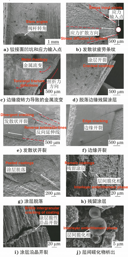
The ball valve was observed under a scanning electron microscope, and the results are shown in Figure 2. At the hinge between the valve stem and the ball valve, the high-frequency rotation of the valve stem causes the formation of sharp-angled pits. The stress caused by the rotation causes obvious tissue distortion of the matrix and fragmentation of the surface oxide layer; all the coatings have fallen off in the stress point area where the rotation force is input and near the stress input point, and there are obvious divergent stripes. The angle between the stripes is about 30°. This is a typical morphology where stress is input into the base material in the form of points and spreads within the base material. The stress has spread divergently into the interior of the matrix at the contact point. Figure 2c shows the morphology of the rotating hinge between the valve stem and the ball valve. A gap gradually forms between the valve stem and the ball valve due to the rotation of the valve stem. As the valve stem rotates, a gap gradually forms between the valve stem and the ball valve. The increase in the gap and the subsequent high-frequency rotation will cause displacement between the two, resulting in obvious metal rheology and scratching on the edge of the ball valve. Figure 2d shows the morphology of the residual coating on the edge of the groove. The residual coating is first flame sprayed and then machined, forming a prismatic coating at the edge that is unsupported and easily falls off; the flame sprayed coating cracks along the divergent stress diffusion direction, and the coating and the substrate are separated. Stress expansion causes the coating to undergo significant brittle cracking (Figure 2e), and the focus of the reverse extension line of the crack propagation direction is the stress input point; there is an obvious lack of fusion between the coating and the substrate, which is the typical characteristics of the mechanical bonding of flame spraying (Figure 2f).
The coating undergoes corrugated peeling under the action of cyclic fatigue stress, and part of the coating remains on the surface of the substrate (Figure 2g and 2h. At the same time, in the area where the coating is completely peeled off, a granular interlayer spherical embrittlement phase can be observed; the fracture surface of the broken coating shows obvious cleavage characteristics (Figure 2i). The internal sharp-angled structure is obvious, which is the surface precipitation under high temperature and a typical morphology of brittle cracking of the coating. After operation, spherical carbides precipitate between the ball valve base and the coating, and the carbides are densely distributed on the surface of the base material. The maximum diameter of the observed carbides is about 10um, and the average diameter is about 6.2um; the average spacing of the precipitated phases is about 18.7um, which is close to the thickness of the coating, blocking the bonding force between the coating and the substrate (Figure 2j).

Figure 2
a) Hinge surface pits and stress input points
c) Metal rheology caused by edge rotation force
b) Divergent fatigue streaks
d) Remaining coatings on the peeled edge
e) Divergent cracking
f) Edge cracking
g) Coating peeling off
h) Residual coatings
h) Residual coatings
i) Intergranular cracking of coatings
j) Interlayer carbide precipitation