1. Design principles
1.1 The analysis of valve operating conditions
Hydraulically controlled slow-closing butterfly valves are divided into two types, that is, heavy hammer types and energy storage types. There are two main operating conditions, including centrifugal pump conditions and hydraulic turbine conditions. Valve-opening centrifugal pump conditions including centrifugal mixed-flow pumps. Start the pump first, and then open the valve after a predetermined time. Open-valve turbine conditions: first, open the bypass valve to balance the pressure, and then open the valve; open the turbine at last. Various operating conditions require the valve to be closed when a shutdown or power failure occurs.
1.2 Types of valves
(1) Heavy hammer types
When the valve is opened, the direction of the solenoid valve is reversed, and the oil pump is started; the hydraulic oil enters the oil cylinder through the flow control valve and the high-pressure hose, and pushes the piston to open the valve. After the valve is opened, the automatic pressure maintaining system starts; the motor continues to charge the pressure maintaining energy, and stops when the pressure reaches the high-pressure set point. Turn the flow control valve handwheel to adjust the valve's opening time. When the valve is closed, the solenoid valve's direction is changed, and the pressure oil in the cylinder returns to the fuel tank through the fast and slow throttle valves, high-pressure hoses, and solenoid valves. When the heavy hammer falls, the butterfly plate rotates to close the valve, quickly cutting off most of the water flow in the first 70% of the stroke, and slowly closing the last 30% of the stroke. The fast and slow closing angle and the time of each stage can be adjusted according to the actual working conditions of the pipeline, which can effectively eliminate the water hammer of the pipeline.
(2) Energy storage types
When the valve is opened, the solenoid valve changes direction, the accumulator releases energy; the hydraulic oil enters the oil cylinder through the speed regulating valve, the one-way valve and the high-pressure hose, and pushes the piston to move; the valve opens according to the set procedure, and the butterfly plate opens to the mechanical limit. Set the fully open position.
When the valve is closed, the solenoid valve reverses direction, the accumulator releases energy, and pushes the reverse action of the oil cylinder to drive the butterfly plate to close the valve to the fully closed position according to the set procedure. In the opening and closing process, when the oil pressure of the system is lower than the lower limit set by the pressure controller, the oil pump is automatically opened to store energy for the accumulator. When the energy of the accumulator is stored to the upper limit set by the pressure controller, the oil pump stops running. The electrical and hydraulic parts form a control system, which can realize pump-valve linkage, remote control, PLC programming control operation, and provide DCS contact interface for computer management.
2. Main parameters
Table 1 Technical parameters
| Projects Nominal pressure/MPa |
Parameters 0.6 to 4.0 |
| Nominal diameter/mm | DN300 to 2000 |
| Eliminating water hammer caused by a stopped pump/% Leakages at a fully closed state |
Greater than and equal to 80 Zero leakage |
| Noise/db Computer control |
Less than 80 (1 meter away) DCS passive contact line joint control interface |
3. Structural Design
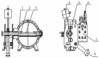
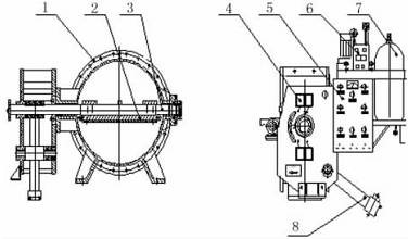
The hydraulically controlled slow-closing butterfly valve is composed of three major parts, that is, the valve body, the hydraulic drive device and the electrical control system; according to the closing power, it is divided into two types, that is, the heavy hammer type and accumulator type. Figure 1 shows the structure of the hammer type hydraulically controlled slow closing butterfly valve, and Figure 2 shows the structure of the accumulator type hydraulically controlled slow closing butterfly valve.

1. Valve bodies 2 Butterfly plates 3. Valve stems 4. Heavy hammers 5. Travel switches
6. Hydraulic stations 7. Electric control cabinets 8. Hydraulic cylinders
Figure 1 Heavy hammer hydraulic control slow closing butterfly valves

1. Valve bodies 2 Butterfly plates 3. Valve stems 4. Travel switches 5. Electric control cabinets
6. Hydraulic stations 7. Accumulators 8. Hydraulic cylinders
Figure 2 Accumulation type hydraulic control slow closing butterfly valves
The heavy hammer type is an early transmission structure, which is characterized by the accumulation of potential energy by the lifted heavy hammer. In the case of an emergency shutdown, the heavy hammer falls rapidly; the potential energy is released; the kinetic energy is increased, and the butterfly plate is quickly closed. The advantage is that the energy accumulation is reliable, and the closing speed is reliable and stable. However, the disadvantage of the heavy hammer type is that it occupies a large space (the radius of rotation of the weight), and the weight of the heavy hammer is heavy. During operation, if the transmission chain is loose, it will cause much vibration.
The accumulator type is a new type of drive mechanism, and its opening and closing are all released by the energy stored in the energy storage tank. It has advantages of small sizes and light weights, and the hydraulic system being very reliable to maintain pressure. It has disadvantages of high costs, higher requirements for the hydraulic system. The valve body and the hydraulic drive device are tightly installed as a whole, which is called a conjoined type, and when they are installed separately, it is called a split type. The integral type has a compact structural structure. The distance between the output oil pipes is short; the flow resistance is small, and the emergency shutdown time is short. The hydraulic station is subjected to much vibration, and it is inconvenient for maintenance and disassembly. The split type places the hydraulic station outside the valve body to avoid the hydraulic station parts from working in continuous vibration. At the same time, it is not necessary to disassemble and assemble the huge hydraulic station to maintain the main body of the valve, but its disadvantage is that it occupies large space, the conveying pipeline is long, and the flow resistance is great, which easily affects the opening and closing speed.
