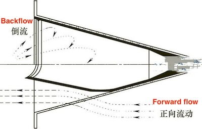
The conical diaphragm check valve features a perforated conical frame that supports the internal diaphragm. It is installed between pipeline flanges or flange joints. As fluid flows through the cone, it lifts the diaphragm off its seat, allowing passage. When the downstream flow stops, the diaphragm promptly returns to its original position, sealing the valve.
As shown in Figure 3, the conical diaphragm check valve consists of a conical diaphragm and a perforated conical frame. The diaphragm, made off selected rubber compounds, is secured to the stainless steel frame with screws and nuts. The valve has a simple, frameless design.
The outer edge of the valve frame is clamped between pipeline flanges and installed within the pipeline, effectively using the pipeline itself as the housing. When fluid flows from the right (Figure 1), the diaphragm, which is firmly attached to the frame, bends under pressure, allowing fluid to pass through the perforations. When fluid flows from the left, the diaphragm presses against the frame, forming a complete seal. This mechanism provides effective backflow prevention.

Figure 1: Conical Diaphragm Check Valve
Due to its unique design and operating mechanism, the conical diaphragm check valve offers several advantages over conventional check valves.
Lacking an external housing, the conical diaphragm check valve utilizes existing pipeline space, making it compact and lightweight. For example, an NPS 8 valve weighs less than 3 kg, making it easy to handle. It requires no special fittings, and its piping configuration is identical to that of conventional valves. This design enhances its compact and lightweight structure while allowing seamless integration with existing valve connections.
Unlike lift and swing check valves, which require specific orientations, the conical diaphragm check valve can operate in any position. Since the diaphragm is the only moving part and is lightweight with high elasticity, the valve is virtually unaffected by gravity. This flexibility is particularly beneficial in space-constrained piping systems.
With only a rubber diaphragm as the moving component, the valve operates with minimal noise, as there is no metal-to-metal contact. This results in lower noise levels than conventional check valves.
The rubber diaphragm serves as an effective sealing component, ensuring a tight seal. Even without back pressure, the diaphragm naturally presses against the frame due to its inherent elasticity. While suitable for both gas and liquid applications, additional considerations may be required for gas sealing due to stricter requirements.
The valve exhibits excellent resistance to vibration and effectively mitigates water hammer effects, similar to a spring-loaded check valve.
With no sliding or impact-prone metal components and minimal leakage, the conical diaphragm check valve is well-suited for gas applications, providing reliable, and long-term performance.
The frame of the conical diaphragm check valve is made entirely of stainless steel, while the diaphragm is typically composed of one of six types of rubber, as shown in Table 1. The selection of diaphragm material depends on the fluid type, considering factors such as concentration, temperature fluctuations, and potential chemical reactions with impurities. Similarly, the frame material must be chosen based on its corrosion resistance to the specific fluid, especially in acidic or alkaline environments where concentration, temperature, and pressure must be carefully evaluated to ensure compatibility.
Since neither valve manufacturers nor rubber producers provide comprehensive corrosion resistance data for all fluids, testing is often necessary. Table 1 outlines the maximum operating pressure values at room temperature; for higher temperatures, a lower pressure threshold must be applied. While metals generally weaken at elevated temperatures, special attention should be paid to polymer materials like rubber, as their degradation behavior differs significantly from that of metals.
Pressure loss depends on factors such as fluid type, temperature, viscosity, and density. This issue is not unique to conical diaphragm check valves but applies to all fluid control equipment. The diaphragm material significantly influences valve performance, as different rubber compositions exhibit varying resistance to deformation. For example, natural rubber deteriorates when exposed to air, limiting its lifespan to one or two years. Therefore, it is not recommended for gas applications, particularly in air systems. Although fluorinated rubber diaphragms are highly resistant to harsh chemicals, they have lower elasticity than other materials, making them unsuitable for gas applications that require strict sealing performance."
The standard practice for selecting a conical diaphragm check valve’s diameter is to match it with the pipeline and associated valves in the system. For instance, a 1-inch pipeline corresponds to a DN25 valve, while a 4-inch pipeline corresponds to a DN100 valve. However, a direct one-to-one diameter match is not always appropriate. Selection should be based on specific operating conditions, ensuring that the pressure differential across the valve does not exceed 0.03 MPa and that flow velocity remains below 4 m/s.
These constraints arise from both the valve’s structural limitations and overall system stability requirements. The pressure differential limit is based on the diaphragm’s static strength, while the flow velocity limit prevents excessive turbulence that could induce diaphragm vibration and fatigue failure.
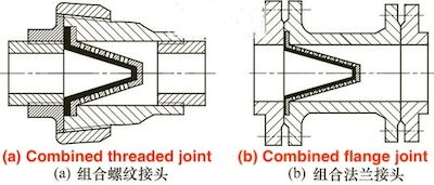
As noted earlier, conical diaphragm check valves are typically installed using flange connections within the pipeline. However, when replacing an existing check valve, installation adjustments may be necessary. In such cases, a combination of threaded and flange joints with short pipe sections, as illustrated in Figure 2, can be used. When using threaded joints, minimizing the flange clamping area is essential to prevent unnecessary bulk and ensure an optimal joint size.

Figure 2 A combination of threaded and flange joints
The standard product range for conical diaphragm check valves covers diameters from DN13 to DN200. For sizes above DN250, a multi-conical valve design is typically required. DN250+ models are not commonly available due to two main factors. First, at larger sizes, the diaphragm’s weight becomes significant relative to its elasticity, reducing valve efficiency. Second, even if design modifications were made to accommodate larger diaphragms, low market demand would result in high production costs.
As with all fluid-handling equipment, minimizing impurities in the medium is critical for conical diaphragm check valves. Since these valves lack metal-to-metal contact points, they are resistant to sticking and overheating caused by impurities. However, the frame contains numerous small openings that can trap fibrous impurities, potentially compromising sealing performance and increasing flow resistance. Therefore, fibrous impurities should be eliminated to the greatest extent possible. Solid impurities smaller than 1 mm can typically pass through the valve unless they adhere to internal surfaces. In gas applications, even fine solid particles can damage the diaphragm’s sealing surface. To prevent this, filtration systems should be used when solid contaminants are present in the gas stream.
During installation or maintenance, care should be taken to avoid damaging the sealing surface. Since the conical diaphragm check valve is not subject to wear, proper usage generally eliminates the need for diaphragm removal or reinstallation. If diaphragm replacement is necessary, installation screws should not be over-tightened. Although there is no specific torque requirement, the diaphragm and frame should be lightly tightened without gaps, and double nuts should be used to prevent loosening. Excessive external force on the diaphragm can cause deformation and compromise sealing performance.
Table 1 Types of diaphragm materials
|
Parts |
Materials |
Primary Applications |
Operating Temperature (°C) |
Maximum Operating Pressure (kgf/cm²) |
|
Cone Frame |
Stainless Steel (SUS316) |
— |
— |
— |
|
Diaphragm |
Natural Rubber |
Water |
20 to 70 |
20 (10 at maximum temperature) |
|
Fluorinated Rubber |
Acids, and inorganic solvent vapors |
0 to 200 |
45 (8.5 at maximum temperature) |
|
|
Nitrile Rubber |
Water, oil, air, and gas |
-15 to 100 |
28 (7.7 at maximum temperature) |
|
|
Ethylene Propylene Rubber |
Water, oil, air, and gas |
-50 to 150 |
20 (4.2 at maximum temperature) |
|
|
Silicone Rubber |
Alkaline solutions, and diluted acids |
60 to 200 |
30 (4.5 at maximum temperature) |
|
|
Ethylene Propylene & Isobutylene Rubber |
Water |
-20 to 100 |
20 (7.0 at maximum temperature) |
Conical diaphragm check valves offer significant advantages across various applications. One common use is serving as a bottom valve in pumps, where its primary advantage is zero-leakage performance, a critical requirement for such valves. Additionally, in pump rooms where installation is difficult, their lightweight design offers a distinct advantage. Their ability to be installed in various orientations further simplifies maintenance.
By making use of existing pipe connections, conical diaphragm check valves can often be installed with minimal modifications. For instance, small-diameter check valves are used in household water meters to prevent backflow in water supply systems, and research on this application is approaching real-world implementation. A key application in gas systems is their role in pneumatic powder conveying, which transports fine materials like cement using compressed air. A check valve prevents powder from flowing back into the compressor. However, traditional lift and swing check valves rely on backflow to close, which allows dust to enter the compressor, leading to increased wear and reduced efficiency. This shortens the valve’s service life to only a few months. Replacing these traditional valves with conical diaphragm check valves effectively mitigates these issues, enhancing performance and ensuring reliable operation.